Spectrum Controls 1794sc-IRT8I User Manual
Page 25
Chapter 2: Installation and Wiring
2-15
User's Manual Pub. 0300242‐01 Rev. A
Section 2.6
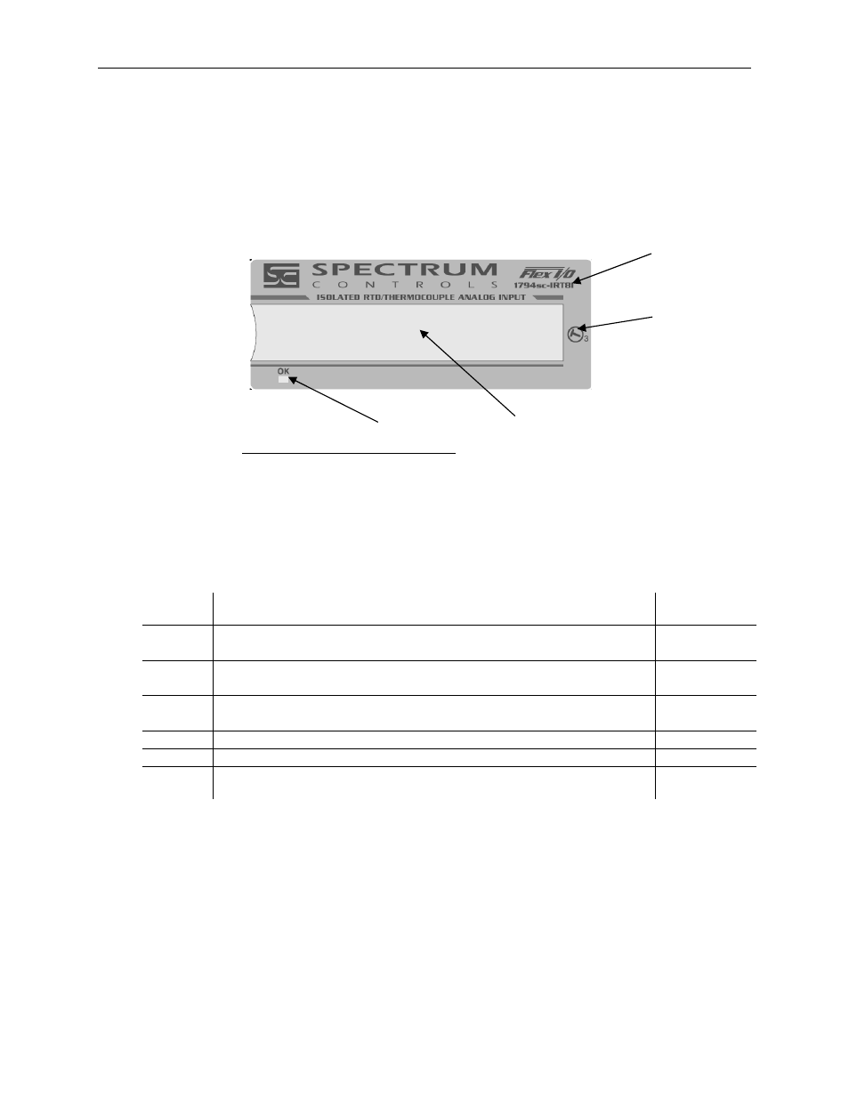
Module Indicators
The IRT8I module has one status indicator (OK) that is on when power is applied and no
hardware faults are present. See figure below.
Item Description
1 Module
Catalog
Number
2
Module key-switch position
3 Removable
label
4 Power/Status
LED
Table 2-4 (Module Status LED)
Module
State
Condition LED
Color
&
State
New
Power up initialized complete and passed Self-Test. Loads stored
configuration, if it exist. Read Module Information Block. (see notes)
RED, blink
@1 Hz
Not
Config
Module has not received configuration from Master. It can Set and
Get attributes. (see notes)
GREEN,
blink @1 Hz
Idle
Controller in Program mode.
Communications normal
GREEN, solid
Active
Controller in Run mode & Communication Is normal
GREEN, solid
Fault
FlexIO Comm. Fault or PU bit is one and /Fault=0
GREEN, solid
Fatal
Fault
Module fails self tests or detects illegal state transition
RED, solid
1
2
3
4
Figure 2-5