Spectrum Controls 1794sc-IRT8I User Manual
Page 22
2-12
Flex™ IO Isolated RTD/Thermocouple Module
User's Manual Pub. 0300242‐01 Rev. A
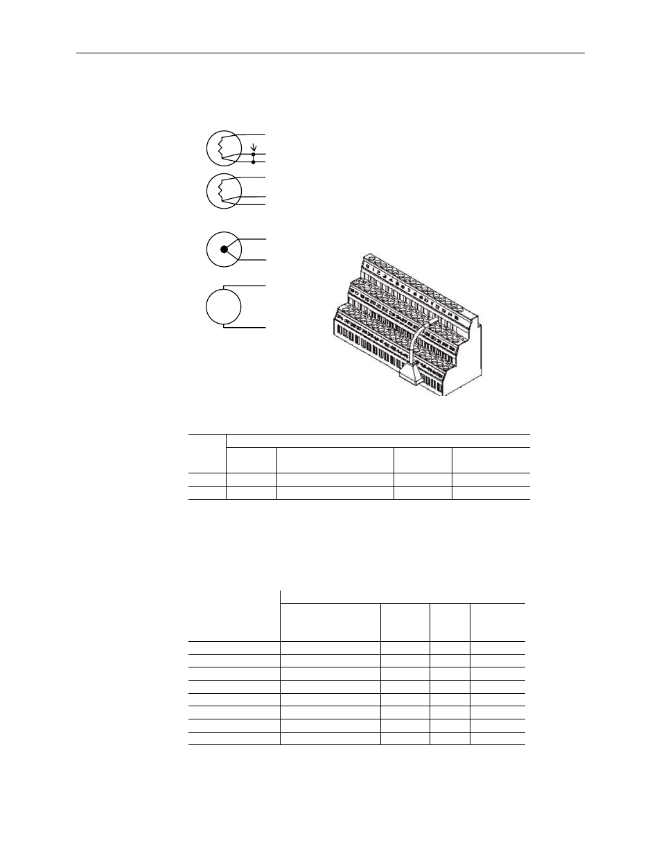
Table 2-2
Input CJC
Sensor
+ Chassis
Ground
- CJC
Tail
1
CJC1 C37
C38
C39
A1
CJC2 C-46
C-47
C-48
B31
1
Terminals 37, 38, and 39, and 46, 47, and 48 are for cold junction
compensation (with 38 and 47 chassis GND). Connect the tail of CJC 1 to
terminal 1 and CJC2 to terminal 31 if channels 0…3 or 0…7 are configured
for thermocouples.
Table 2-3
Channel Number
1794-TB3G and 1794-TB3GS Terminal Base Units
Signal Return (R)
Input +
(IN+)
Input
(-)
I Return
(-)
0 A-0 A-1
A-2
A-3
1 A-4 A-5
A-6
A-7
2 A-8 A-9
A-10
A-11
3 A-12
A-13
A-14
A-15
4 B-17
B-18
B-19
B-20
5 B-21
B-22
B-23
B-24
6 B-25
B-26
B-27
B-28
7 B-29
B-30
B-31
B-32
1Terminals 16, 33, and 40…45 are chassis ground.
+
mV
-
RTD/Resistance
2-wire
0
2
1
3-wire
Thermocouple
1
2
+
-
mV Source
1
2
1
0
2
1
Jumper
Numbers 0, 1, 2, and 3 are wiring numbers of the
sensor used. For terminal numbers corresponding to
R, IN+, IN-, I, refer to Terminal Base Unit Wiring
Connections below.