Spectrum Controls 1794sc-IRT8I User Manual
Page 18
2-8
Flex™ IO Isolated RTD/Thermocouple Module
User's Manual Pub. 0300242‐01 Rev. A
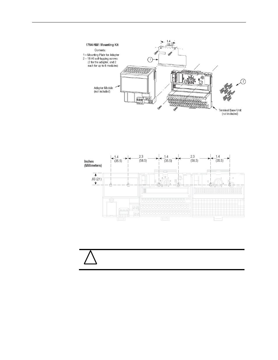
To install the mounting plate on a wall or panel:
1) Lay out the required points on the wall/panel as shown in the drilling dimension
drawing.
Drilling Dimensions for Panel/Wall Mounting of Flex IO
2) Drill the necessary holes for the #6 self-tapping mounting screws.
3) Mount the mounting plate (1) for the adapter module using two#6 self-tapping
screws (18 included for mounting up to 8 modules and the adapter).
!
Attention
Make certain that the mounting plate is properly grounded to the
panel. Refer to “Industrial Automation Wiring and Grounding
Guidelines,” publication1770-4.1.
4) Hold the adapter (2) at a slight angle and engage the top of the mounting plate in
the indention on the rear of the adapter module.
5) Press the adapter down flush with the panel until the locking lever locks.
6) Position the terminal base unit up against the adapter and push the female bus
connector into the adapter.
7) Secure to the wall with two #6 self-tapping screws.
8) Repeat for each remaining terminal base unit.