Spectrum Controls 1794sc-IRT8I User Manual
Page 15
Chapter 2: Installation and Wiring
2-5
User's Manual Pub. 0300242‐01 Rev. A
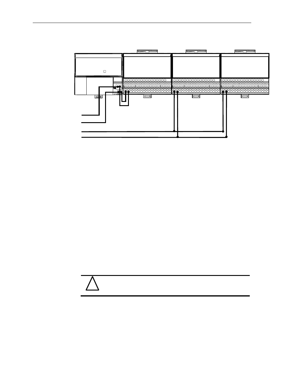
Wiring when total current draw is greater than 10A
Combination
Note: All modules powered by the same power supply must be frequency
or IRT8I modules for this configuration.
Total current draw through any base unit must not be greater than
10A
Section 2.4
Installing the
Module
Installation of the analog module consists of:
• Mounting the terminal base unit
• Installing the IRT8I module into the terminal base unit
• Installing the connecting wiring to the terminal base unit
If you are installing your module into a terminal base unit that is already installed,
proceed to “Mounting the IRT8I Module on the Terminal Base Unit” on page 2-9.
2.4.1 Mounting the Terminal Base Unit on a DIN Rail
!
Attention
Do not remove or replace a terminal base unit when power is applied.
Interruption of the flexbus can result in unintended operation or
machine motion.
1) Remove the cover plug (if used) in the male connector of the unit to which you
are connecting this terminal base unit.
2) Check to make sure that the 16 pins in the male connector on the adjacent device
are straight and in line so that the mating female connector on this terminal base
unit will mate correctly.
24 VDC
24 VDC
Power
Frequency Input
Module
IF8u
Module
Frequency Input
Module