Spectrum Controls 1794sc-IRT8I User Manual
Page 19
Chapter 2: Installation and Wiring
2-9
User's Manual Pub. 0300242‐01 Rev. A
Note: The adapter is capable of addressing eight modules. Do not exceed a
maximum of eight terminal base units in your system.
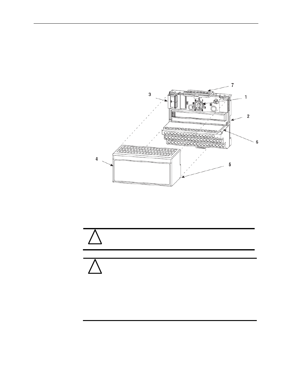
2.4.3 Mounting the IRT8I Module on the Terminal Base Unit
The IRT8I isolated input module mounts on a 1794-TB3G or TB3GS terminal base unit.
1) Rotate the key-switch (1) on the terminal base unit (2) clockwise to position 3 as
required for the IRT8I module.
2) Make certain the flexbus connector (3) is pushed all the way to the left to
connect with the neighboring terminal base/adapter. You cannot install the
module unless the connector is fully extended.
3) Make sure that the pins on the bottom of the module are straight so they will
align properly with the connector in the terminal base unit.
!
Attention
This module is UL listed only when used with listed Allen-Bradley
catalog numbers 1794-TB3G or TB3GS terminal base units.
!
Attention
Remove field-side power before removing or inserting the module.
This module is designed so you can remove and insert it under
backplane power. When you remove or insert a module with field-side
power applied, an electrical arc may occur. An electrical arc can cause
personal injury or property damage by:
• sending an erroneous signal to your system’s field devices
causing unintended machine motion
• causing an explosion in a hazardous environment
Repeated electrical arcing causes excessive wear to contacts on both
the module and its mating connector. Worn contacts may create
electrical resistance.
4) Position the module (4) with its alignment bar (5) aligned with the groove (6) on
the terminal base.
5) Press firmly and evenly to seat the module in the terminal base unit. The module