Spectrum Controls 1762sc-OF8 User Manual
Page 30
3-10
MicroLogix™ 1200 IO 8 Ch Output Module
User’s Manual Pub. 0300246-01 Rev. B
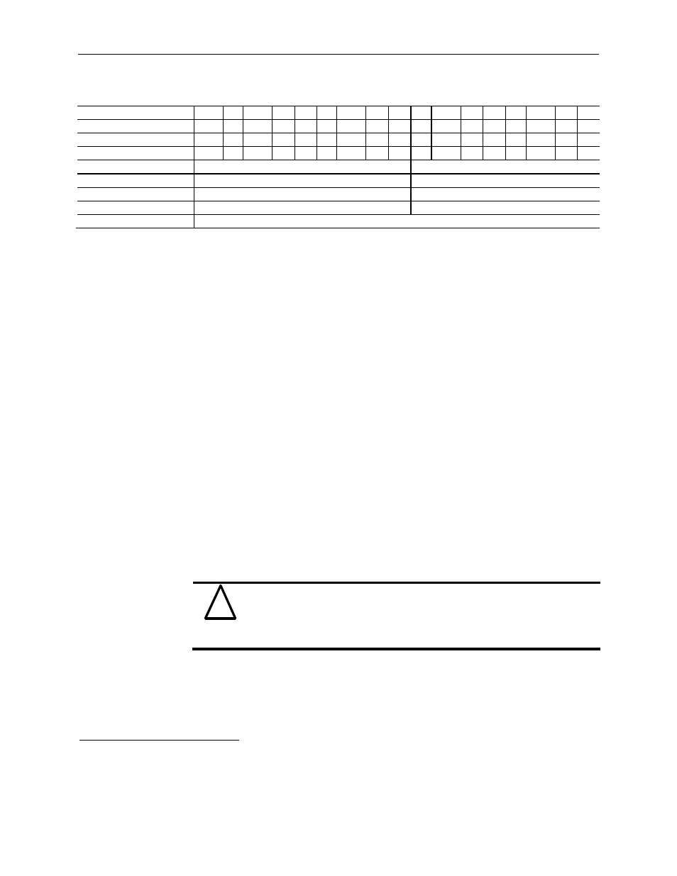
Table 3-8 (Input Words - Normal Run Mode)
Word
Bit
15
14
13
12
11
10 9 8 7 6 5 4 3 2 1 0
General Status (Word 0) I:e.0 -
-
-
-
-
-
-
-
S7
S6
S5 S4 S3
S2
S1
S0
Output Status (Word 1) I:e.1 - LD3 U3 O3
- LD2 U2 O2
-
LD1 U1 O1
-
LD0 U0 O0
Output Status (Word 2) I:e.2 - LD7 U7 O7
- LD6 U6 O6
-
LD5 U5 O5
-
LD4 U4 O4
Echo Config (Word 3)
7
7
Echo Config (Word 4)
7
2 Config> 7 Echo Config (Word 5) 7 4 Config> 7 Echo Config (Word 6) 7 6 Config> 7 Not Used (Word 7) 0x0000 - = Not used. Bit set to 0. S = General status bit. If a bit is set (1) then there is an error associated with that channel (i.e. U = Under range flag. When set to 1, indicates the output word value set by the user is below the O = Over range flag. When set to 1, indicates the output word value set by the user is above the LD short circuit. If the channel is configured for current mode, open circuit is Section 3.6 The following ladder sample demonstrates how to configure the module when the PLC ! Attention Use the “Command” bit (B3:0/0) in the following ladder sample as a 7 See Table 3-3 (Data Words 1 through 4)
under/over range).
defined Low Range value (see Output Data Format table). The channel will
output voltage or current (depending on the range type) to the Low Limit
value.
defined High Range value (see Output Data Format table). The channel will
output voltage or current (depending on the range type) up to the High Limit
value.
indicated. The error bit is cleared (0) at the time the condition is cleared.
Configuration
Ladder Sample
transitions from Program to Run, using the process described in Section 3.4.
condition before any instruction that writes data to one of the 8 module
output words. Failure to do so can result in the module rejecting the
configuration and not going into run mode (i.e. a rapid blinking module
status LED).