Ch 3 – Speck Electronics MicPre 5.0 User Manual
Page 29
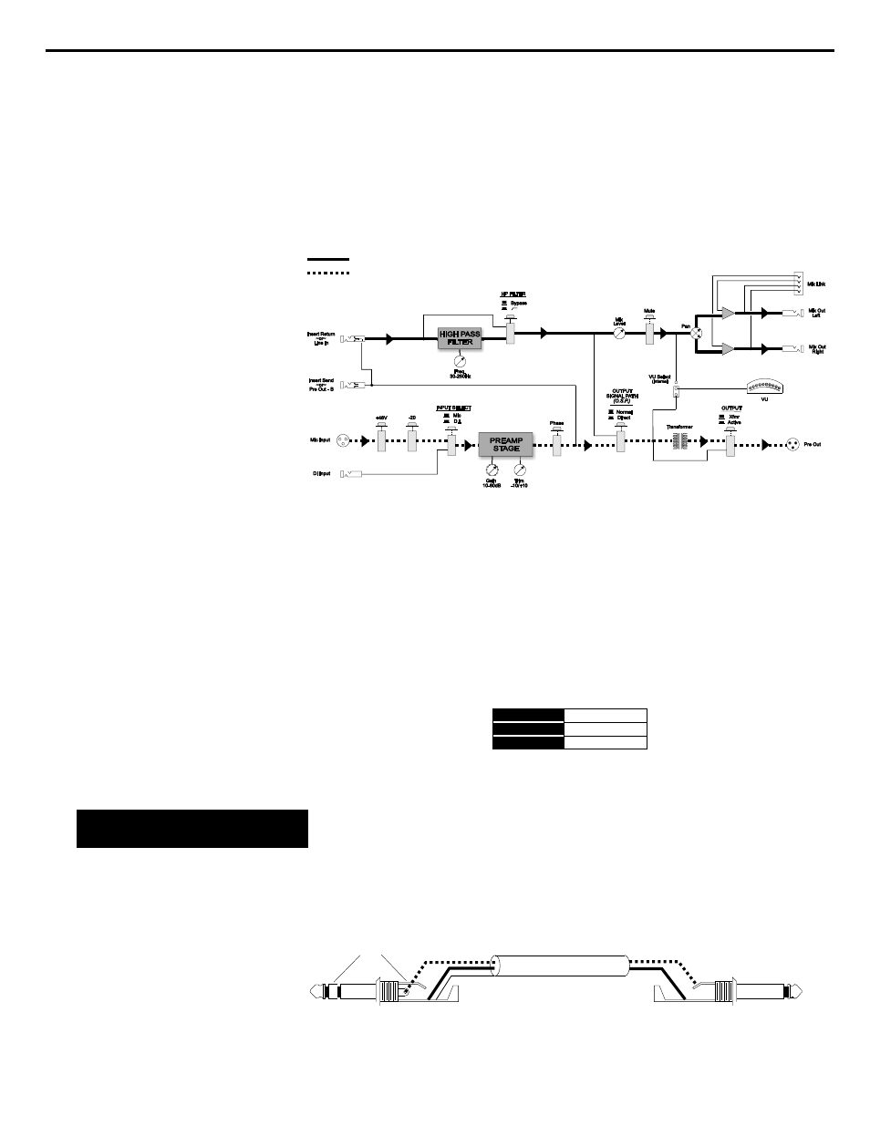
The signal flow diagram below (Figure 12) shows two separate
signal paths with the "mic to pre out" shown in a dashed line and
the "line in to mix out" as a solid bold line.
These "Active-Balanced" TRS jacks are the left and right outputs
for the mix section. The signal present at these jacks are adjusted
by the mix level and pan controls on the front panel.
The mix outputs are available for interface to the input of an
external console, HDR, DAW, etc. The mix out jacks are wired as
shown below in Figure 13.
Do not use the mix out jacks with an unbalanced input. When
wiring unbalanced cables and connectors, care must be taken not
to connect the low terminal (ring) to ground.
Any unbalanced ¼" plug interfaced to this jack should be wired
according to the diagram shown below in Figure 14.
21. Mix output jacks
HIGH
HIGH
LOW
LOW
GROUND
GROUND
TIP
TIP
RING
RING
SLEEVE
SLEEVE
Figure 13. Wiring for mix output jacks
Figure 12. Flow diagram for split signal path
Chapter 3
Operation Section
23
Wiring the MP 5.0
to unbalanced inputs
"Line In to Mix Out" signal path
"Mic input to Pre Out" signal path
Figure 14. Unbalanced wiring for TRS outputs
Shield
To MP 5.0 output jack
To unbalanced input
Do not connect
ring terminal