Ch 2, Mix link connector – Speck Electronics MicPre 5.0 User Manual
Page 15
PIN 2
PIN 2
PIN 3
PIN 3
PIN 4
PIN 4
PIN 5
PIN 5
PIN 6
PIN 6
PIN 6
PIN 6
PIN 8
PIN 8
Mix Out - Left
Mix Out - Left
Mix Out - Right
Mix Out - Right
Ground
Ground
Sum In- Left
Sum In- Left
Sum In - Right
Sum In - Right
Ground
Ground
PIN 1
PIN 1
Figure 3. Pin-outs for mix link connector
Chapter 2
Installation Section
9
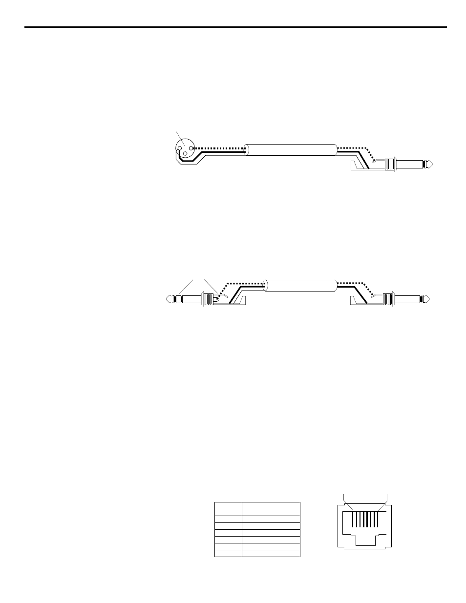
If wiring the XL Pre Out for unbalanced operation, the cable
should be wired according to the diagram shown below in
Figure 1.
If wiring the Insert Send (Pre Out-B) or Mix Outs for unbalanced
operation, the cable should be wired according to the diagram
shown below in Figure 2.
The Mix Link connector (6) is a RJ45 modular jack that allows the
mix section of the MP 5.0 to be combined with additional
MP 5.0's. The terminals on the mix link connector include the
left/right mix outputs and the left/right summing inputs.
A selection of standard and custom interface cables used to link the
MP 5.0’s are available from Speck Electronics or may be
assembled using standard 8 pin RJ45 modular plugs and 4
conductor cable.
The Pin-outs for the mix link connector are shown below in
Figure 3.
Mix Link Connector
1
8
Figure 1. Unbalanced wiring for XL output
Shield
Shield
To MP 5.0 XL output
To unbalanced input
Do not
connect pin 3
1
2
3
Figure 2. Unbalanced wiring for TRS outputs
Shield
To MP 5.0 output jack
To unbalanced input
Do not connect
ring terminal