Ch 3, Rear panel, Microphone input 17. preamp output – Speck Electronics MicPre 5.0 User Manual
Page 26
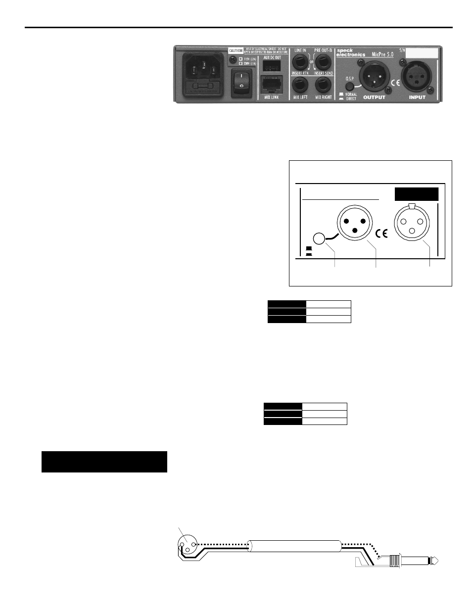
Rear Panel
This microphone input XL connector is used to connect a low
impedance microphone.
The mic input is selected
with the Mic/DI switch on
the front panel. Before
connecting your
microphone, it is
recommended to set the
Gain to the 10dB setting
and the 48V phantom
power switch to the off
position. The mic input XL
connector is wired as
shown below in Figure 5.
This is the main output of the preamp. This XL output may be
“Transformer-Balanced” or “Active-Balanced” depending on the
switch setting on the front panel. The pre out XL connector is
wired as shown below in Figure 6.
Do not use the XL preamp output with an unbalanced input. When
wiring unbalanced cables and connectors, care must be taken not
to connect the low terminal (pin 3) to ground.
Any unbalanced XL plug interfaced to this connector should be
wired according to the diagram shown below in Figure 7.
16. Microphone input
17. Preamp output
HIGH
HIGH
LOW
LOW
GROUND
GROUND
PIN 2
PIN 2
PIN 3
PIN 3
PIN 1
PIN 1
HIGH
HIGH
LOW
LOW
GROUND
GROUND
PIN 2
PIN 2
PIN 3
PIN 3
PIN 1
PIN 1
Figure 5. Mic input wiring
Figure 6. Pre output wiring
18
17
16
DIRECT
OUTPUT
INPUT
speck
electronics
S/N
MicPre 5.0
O.S.P.
NORMAL
1
2
1
2
3
3
Chapter 3
Operation Section
20
Wiring the MP 5.0
to unbalanced inputs
Figure 7. Unbalanced wiring for XL output
Shield
Shield
To MP 5.0 XL output
To unbalanced input
Do not
connect pin 3
1
2
3