Pecifications – Southbend SL-Series User Manual
Page 4
E
LECTRIC
C
ONVECTION
O
VENS
OPERATOR’S MANUAL 1181958 REV 5 (4/14)
PAGE
4
OF 47
S
PECIFICATIONS
NOTICE
The appliance, when installed, must be electrically grounded and comply with local codes, or in the absence of local
codes, with the National Electrical Code, ANSI/NFPA 70, or the Canadian Electrical Code, CSA C22.2, as applicable.
Southbend reserves the right to change specifications and product design without notice. Such revisions do not entitle
the buyer to corresponding changes, additions, or replacements for previously purchased equipment.
This product is intended for commercial use only, not for household use.
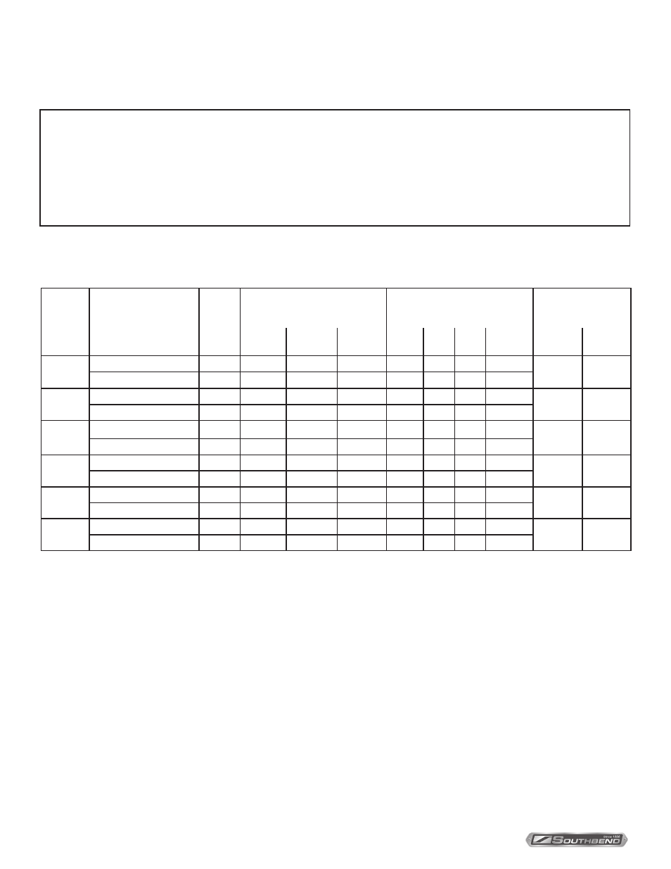
ELECTRICITY SUPPLY
Supply
Voltage
Oven Component
Total
kW
3-Phase Loading (kW/phase)
Nominal Amperes per Line-
Wire
3-Phase
Minimum Supply
Wire (AWG) Size
L1-L2
L2-L3
L1-L3
L1
L2
L3
1-Phase
Total
1-Phase 1-Phase
480
Heating Elements
11.00
3.67
3.67
3.67
13.2
13.2
13.2
22.9
12
10
Motor & Controls
0.90
0.00
0.00
0.00
2.2
0.0
2.2
2.2
415
Heating Elements
11.00
3.67
3.67
3.67
15.3
15.3
15.3
45.9
12
6
Motor & Controls
0.90
0.00
L3-N
0.90
0.0
0.0
3.8
3.8
380
Heating Elements
11.00
3.67
3.67
3.67
16.7
16.7
16.7
28.9
12
8
Motor & Controls
0.90
0.00
L3-N
0.90
0.0
0.0
4.1
4.1
240
Heating Elements
11.00
3.67
3.67
3.67
26.4
26.4
26.4
45.8
8
6
Motor & Controls
0.90
0.00
0.00
0.90
3.8
0.0
3.8
3.8
220
Heating Elements
9.25
3.10
3.10
3.10
24.2
24.2
24.2
42.0
8
6
Motor & Controls
0.90
0.00
0.00
0.90
4.1
0.0
4.1
4.1
208
Heating Elements
11.00
3.67
3.67
3.67
30.5
30.5
30.5
52.9
8
4
Motor & Controls
0.90
0.00
0.00
0.90
4.3
0.0
4.3
4.3
An electrical diagram is located on the side of the control panel assembly (see drawing on page 35). Electrical
diagrams can also be found in this manual beginning on page 36.
The electrical connections are made directly to the terminals of the heating-element contactor, which is located
inside the control-panel compartment on the right side of the oven. A circular opening sized for a strain-relief
fitting is located on the back of the oven near the right side (right as seen from the front of the oven, see illus-
tration on page 16). Models with two stacked ovens have a separate electrical connection for each oven.
Use 167°F (75°C) wire for all supply lines.
Ovens are shipped wired for either single-phase or three-phase operation, depending on which was specified
on the factory order. If necessary, an oven can be field-converted to use either single-phase or three-phase
power (see page 32).
S
PECIFICATIONS
The following table lists the electricity supply requirements PER OVEN (double for dual-oven models).