Roubleshooting – Southbend SL-Series User Manual
Page 36
E
LECTRIC
C
ONVECTION
O
VENS
OPERATOR’S MANUAL 1181958 REV 5 (4/14)
PAGE
36
OF 47
WIRING DIAGRAMS
A wiring diagram is located on the side of the control panel assembly (as shown on page 35). Wiring diagrams also
appear on the following pages of this manual. Which wiring diagram is appropriate depends on the voltage and type of
controls.
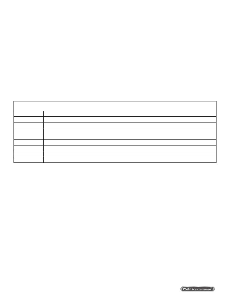
Index of Wiring Diagrams
Page Number
Voltage and Type of Controls
37
208-240 Volt Models with Standard Controls
38
480 Volt Models with Standard Controls
39
415/240 Volt Models with Standard Controls
40
380/220 Volt Models with Standard Controls
41
208-240 Volt Models with Cycle/Cook & Hold Controls
42
480 Volt Models with Cycle/Cook & Hold Controls
43
415/240 Volt Models with Cycle/Cook & Hold Controls
44
380/220 Volt Models with Cycle/Cook & Hold Controls
T
ROUBLESHOOTING
BLOWER WHEEL REPLACEMENT
To replace the blower wheel, do the following:
1. Remove racks and rack guides.
2. Remove rear air baffle in front of blower wheel.
3. Loosen the two square heads on blower wheel hub.
4. Pull blower wheel from motor shaft. If blower wheel is difficult to pull off, use puller
disk (available from Southbend as part number 1179100).