System framework, 1 block diagram – OPTI-UPS DS200KC33II User Manual
Page 4
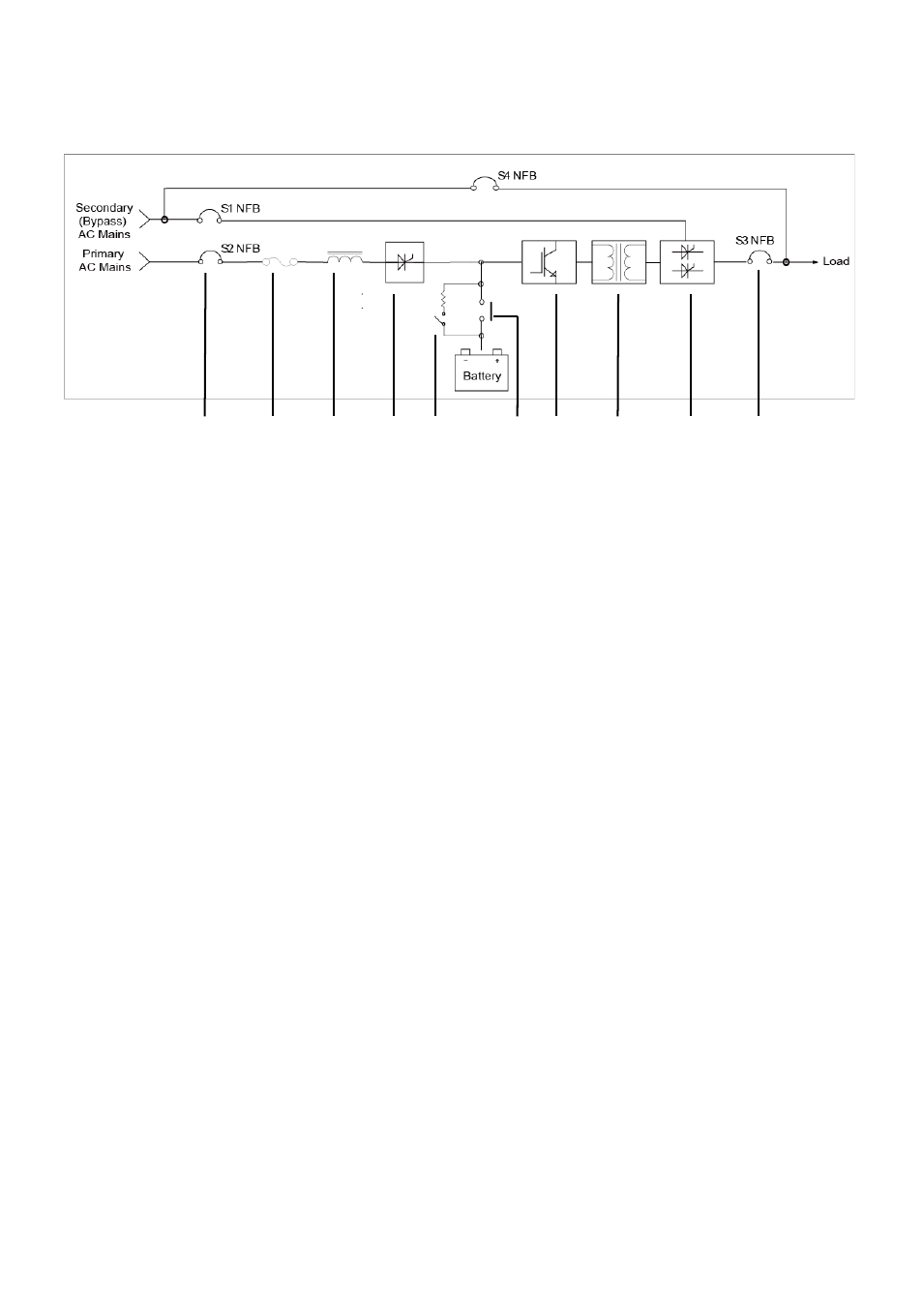
2. System Framework
2-1 Block Diagram
(1)
(8)
(2) (3) (4) (5) (6) (7) (9) (10) (11) (12)
Fig. 2-1
(1) Secondary (Bypass) AC Mains NFB (S1 NFB)
(2) Primary AC Mains NFB (S2 NFB)
(3) Input Fuse
(4) Three-phase AC Inductor
(5) Rectifier/ Charger
(6) Battery Auxiliary Relay
(7) Battery MS (Magnetic Switch)
(8) Manual Bypass Maintenance NFB (S4 NFB)
(9) Inverter Module
(10) Inverter Isolation Transformer
(11) STS (Static Transfer Switch)
(12) Output NFB (S3 NFB)
This manual is related to the following products: