Nor-Cal CDG 025 OP Lit User Manual
Page 18
18
CDG025-OP-LIT (2010-1)
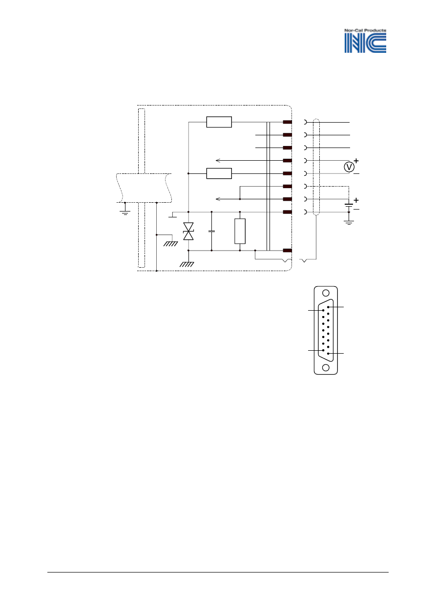
If no sensor cable is available, make one according to the
following diagram.
15
8
9
1
D-Sub,15-pole
female
soldering
side
Electrical connection
Pin 2
Signal Output
Pin 5
Supply common, GND
Pin 7, 11 Supply
Pin 10
Gauge identification Inficon
Pin 12
Signal common
Pin 13
RS232, TxD
Pin 14
RS232, RxD
Pin 15
Housing (Chassis Ground)
case
Connector case
case
10
Ident
13
14
2
TxD
RxD
12
7
11
5
100k
15
100nF
18 V
10
Connect the sensor cable to the gauge and secure it using
the lock screws.
Connect the sensor cable to the controller.