8 rubber valves – Martin Christ Beta 2-8 LSCplus User Manual
Page 36
Beta 1-8 LSC&
Beta 2-8 LSC&
5 Set-up and connection
36
Version 04/2013, Rev. 1.1 of 16/12/2013 • sb
Translation of the original operating manual
Pos: 109 /20 0 Ch rist/3 60 G T-BA L abo r-Pilot (STANDARDMODU LE)/0 50 Aufst ellun g un d Anschl uss/0 50- 010 0 G um miventil e @ 9 \mo d_1 319 531 8057 44_ 68. docx @ 52 539 @ 2 @ 1
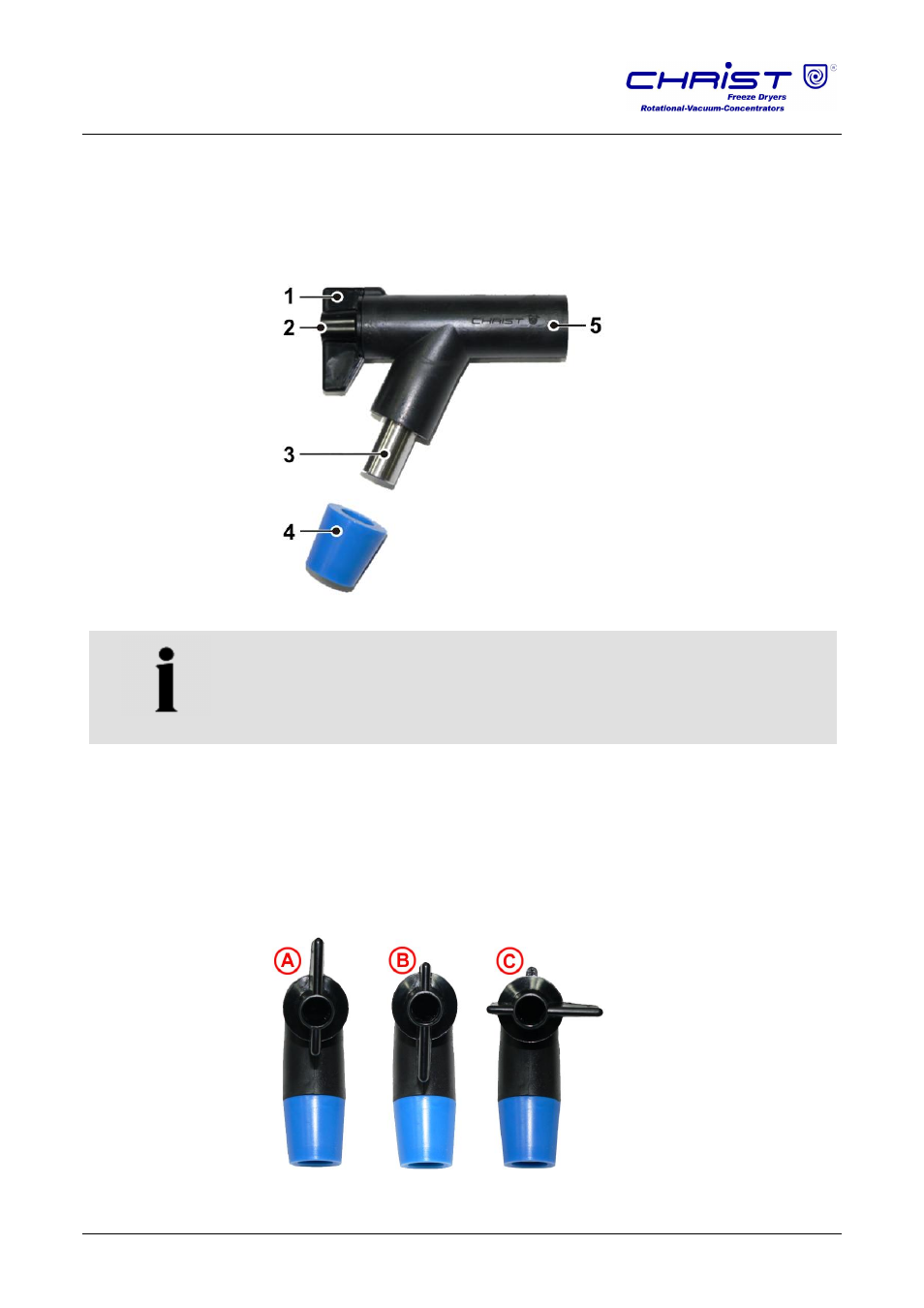
5.8 Rubber valves
The rubber valves (part no. 121860) enable the connection of round-bottom
flasks, wide-neck filter bottles, or distributors for ampoules to a manifold or
drying chamber. Depending on the connector of the components, the blue
plug can be removed.
1
Locking handle
2
Aeration connection
3
Vessel connection
4
Rubber plug
5
Connection to freeze-
dryer (e.g. via a
manifold)
Fig. 18: Rubber valve
NOTE
The rubber valves come supplied in an ungreased state. This is why a thin
layer of vacuum grease must be applied to the connector of the freeze-
dryer as well as to the vessel connector prior to start-up in order to ensure
trouble-free operation.
In position A (see figure below), the aeration connector is open and the
vessel connector is closed. The accessory will be aerated while the vacuum
inside the drying chamber is maintained. As a result, vessels can be
exchanged without any interruption of the drying process.
In position B, the aeration connector is closed and the vessel connector is
open. The connected accessory is connected to the freeze-dryer.
In position C, the aeration connector and the vessel connector are closed.
Fig. 19: Possible positions of the locking handle
Pos: 110 /01 0 Univ ersal mod ule/ Sei tenwe chsel @ 0\ mod _12 021 1624 431 2_0 .docx @ 1 05 @ @ 1
Pos: 111 /01 0 Univ ersal mod ule/ Ab schnitt swechs el @ 0 \mo d_1 202 124 514 062_ 0.d ocx @ 418 @ @ 1