0 typical wiring diagram --- (alarm only) – Labconco Guardian 1000 Digital Airflow Monitor User Manual
Page 15
15
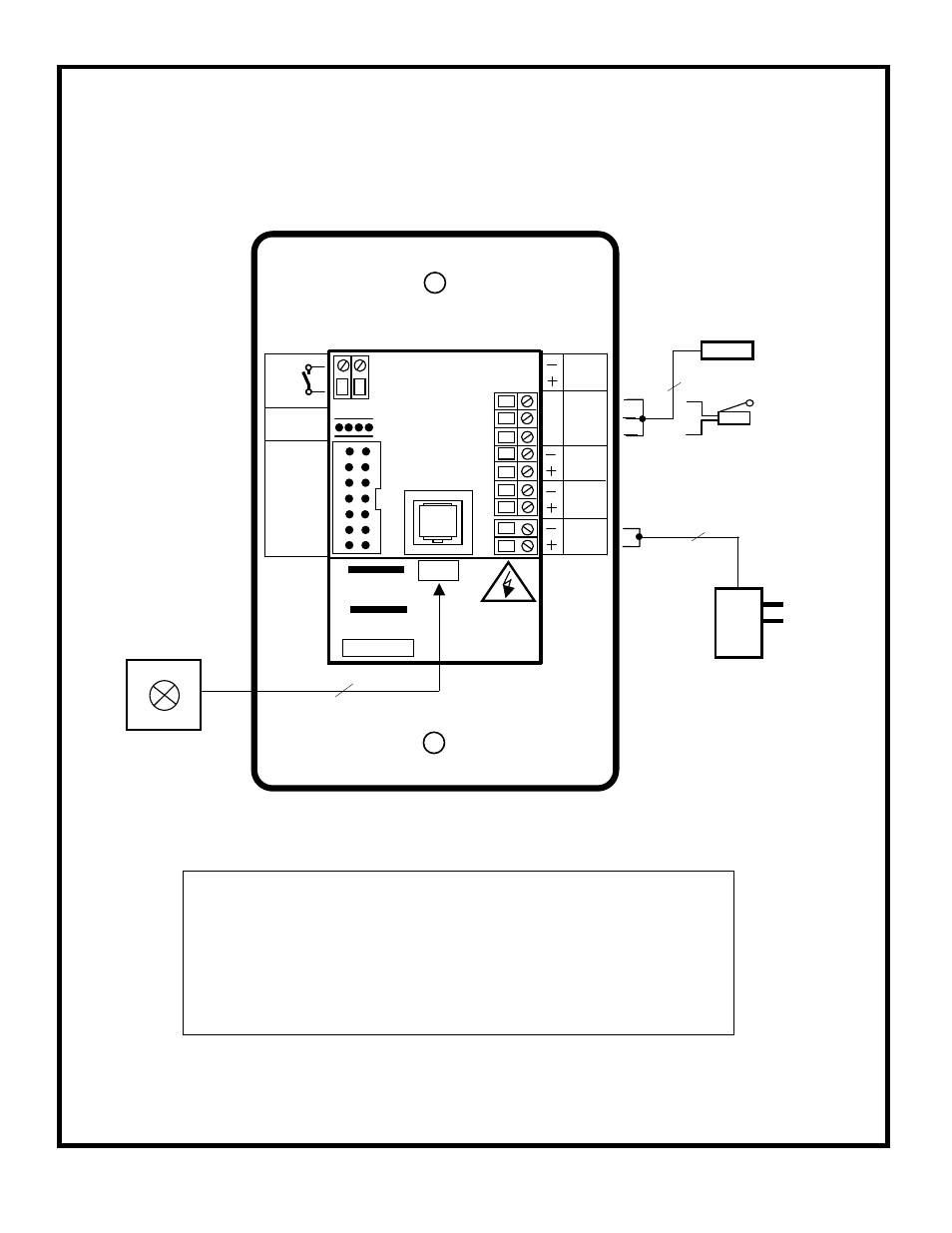
5.0 Typical Wiring Diagram --- (Alarm only)
120V
PSU
120V / 15V DC
Plug – in power
adapter for 120V
socket
Flying lead with plug
connection for PCB
15 V DC
Flying lead with RJ11
plug connection for PCB
and SM6 airflow sensor
12V DC
Sash High
Proximity switch
( Optional )
SM6 or Inline
Airflow Sensor
OUTPUT
RELAY
R1
SENSOR
SOCKET
0-10V
OUTPUT
1
15V DC
POWER
SUPPLY
INPUT
REFER TO
INSTALLATION
INSTRUCTIONS
BEFORE
CONNECTING
MADE IN ENGLAND
www.tel-uk.com
TEL
INPUT 3
Blu
Blk
Brn
AFA 1000 USA
Sash High
Micro - switch
( Optional )
IDC
14-way
Connector
for remote
Interface Box
( Optional )
INPUT 2
INPUT 1
RS 232
Com
Port
Note :
Output 1 is an optional extra output giving a 0 –10 V DC
signal proportional to the Fume Hood face velocity over the
range of 0 – 200 fpm. ( Not included with the standard alarm )
s/w
+
-