Physical overview - ht b18, Operation/connection area of computer – Hatteland Display HT B18 (Fanless) User Manual
Page 23
23
IND100133-40
COM1,2 Serial Port INPUT/OUTPUT:
Supports RS-232 or RS-232/RS-422 or RS-485 using D-SUB 9P Male connectors. Fasten the cable to the connector
using the provided screws on the cable housing itself.
DVI-D OUT:
Connect your DVI cables to the DVI-D 24P Connectors (female) on the rear side of the unit. Screw the DVI cables to
the connectors and make sure you don’t bend any of the pins inside the cable connector when connecting.
Note: For
1920x1200 and 1600x1200 resolutions, DVI must be set to CVT-RB (Coordinated Video Timing-Reduced Blanking)
mode manually to avoid intermittent flickering of the displayed image.
RGB OUTPUT:
Will output a signal from the computer for use with external display or monitor. Connects via a High Density D-SUB
15P Female connector. Fasten the cable to the connector using the
provided screws on the cable housing itself.
Note for DVI and RGB outputs:
You can either use 2 x DVI-D outputs or 1 x DVI-D + 1 x DB15F (RGB/VGA), but not all 3 at once. It is important that
you connect display units BEFORE you boot up the computer. Once inside a booted Operating System (OS),
detection of connected or disconnected units will not be successfull as the hardware and OS driver does not allow
for realtime detection. In case of loss of signal, turn the unit off by pressing the front power button, reconnect signal
cables and power on+boot up again.
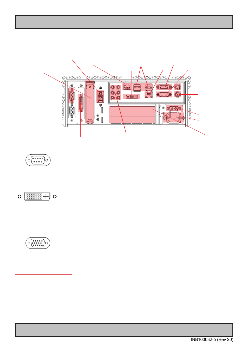
Operation/Connection area of computer
Physical Overview - HT B18
AC Power Input
Keyboard Port
Mouse Port
Network #2
DVI-D OUT (D1)
COM1 RS-232
COM2
RS-232
RS-422
RS-485
Replaceable 2.5 SSD
Hard Drive
Audio IN/OUT Connectors
DC Power Input
DVI-D OUT (D2)
USB 1,2,3,4
Network #1
RGB/VGA OUT
2 x PCI Slots
Reset Button, Power LED & Button
HDD LED