Installation – Hanna Instruments HI 504910 User Manual
Page 6
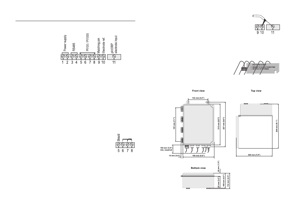
10
11
INSTALLATION
• Remove the connectors protecting shield and wire the meter
as explained below.
• Power supply input (24V AC/DC): connect a 2-wire power
cable (with a minimum cross area of 0.75 mmq) to the
terminals #1 and #2.
If using a DC supply, connect the positive wire to the termi-
nal #1.
• RS485 serial interface (for communicating with HI 504
controller or PC/modem/GSM module):
connect a twisted
shielded cable to terminals #3 (B) and #4 (A).
Note
The serial interface of the HI 504910 Digital Transmitter is
optoisolated. Do not connect the serial cable shield to the
transmitter.
• Pt100/Pt1000 terminals: use these contacts to connect
the Pt100/Pt1000 temperature sensor for automatic tem-
perature compensation of pH measurement.
In the case of shielded wire, con-
nect the shield to pin #5.
In the case of a 2-wire sensor con-
nect the Pt100/Pt1000 to pins #7
and #8, and short pins #6 and #7
with a jumper wire.
If the Pt100/Pt1000 has more than 2 wires, connect the
two wires of one end to pins #6 and #7 (pin #6 is an
auxiliary input to compensate for the cable resistance) and
one wire from the other end to pin #8. Leave the fourth
wire unconnected, if present.
Note
The instrument automatically recognizes the sensor type (Pt100
or Pt1000).
• pH or ORP electrode: connect the
shield of the electrode coaxial cable
(electrode reference) to the terminal
#10, and the electrode coaxial
cable core to terminal #11.
To benefit from the differential (symmetrical) input, connect
the proper electrode wire or a cable with a potential match-
ing pin (grounding bar) to the relevant terminal (#9).
If the matching pin is not available, short pins #9 and #10.
Note
All connected cables should end with cable lugs.
Note
After wiring, always reat-
tach the protecting shield.
DIMENSIONS