Mechanical layouts – Hanna Instruments HI 5000 User Manual
Page 4
4
pH
0
1
2
0
1
2
mS
ALARM
pH
0
SECONDS
mS
2.0
0
TIMER
MINUTES
90
PROPORTIONAL SETTINGS
4
7
0
SECONDS
pH
2.0
0
TIMER
MINUTES
90
PROPORTIONAL SETTINGS
1
4
SLOPE CAL
ALARM
ON
OFF
0.5
1.5
SET
FERT
mS
OFFSET
SLOPE
ALARM
ON
OFF
0.5
1.5
SET
ACID
ALARM
HI 9913
1
10
2.5
5
7.5
1
10
2.5
5
7.5
ALARM
pH
5
6
EC
mS
FEED
FEED
2
3
SET pH
SET EC
ALARM
LINE
ACID
ALK
LCD DISPLAY
CALIBRATION
TRIMMERS
CONTROL KNOBS
AND SWICHES
DOSING TERMINALS
POWER SUPPLY
TERMINALS
ALARM CONTACTS
MATCHING PIN
ZERO CAL
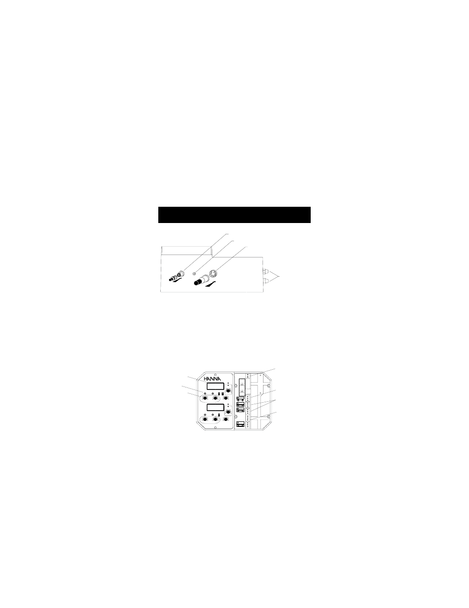
Fig. 2
Figure 2 illustrates the controls and terminals.
MECHANICAL LAYOUTS
MECHANICAL LAYOUTS
MECHANICAL LAYOUTS
MECHANICAL LAYOUTS
MECHANICAL LAYOUTS
BNC CONNECTOR
MATCHING PIN FOR GROUND PROBE
DIN CONNECTOR
WIRING ACCESS
PORTS
Fig. 1
The controllers come equipped with relays operating at a maximum of
2A (240V).
They incorporate a triple contact alarm system. When activated, the
alarm contacts will open or close, triggering the mechanism of your
choice, whether a buzzer, light or any other electrical device.
The controllers are housed in a rugged, modular, fiber-reinforced ABS
housing.
All models can be wired to work with 110/115V or 220/240V at
50/60 Hz power supplies.
Figure 1 illustrates the connector for pH electrode, matching pin
connection, conductivity/TDS probe and the wiring access ports.