Part names and functions – Denon AVR-785 User Manual
Page 16
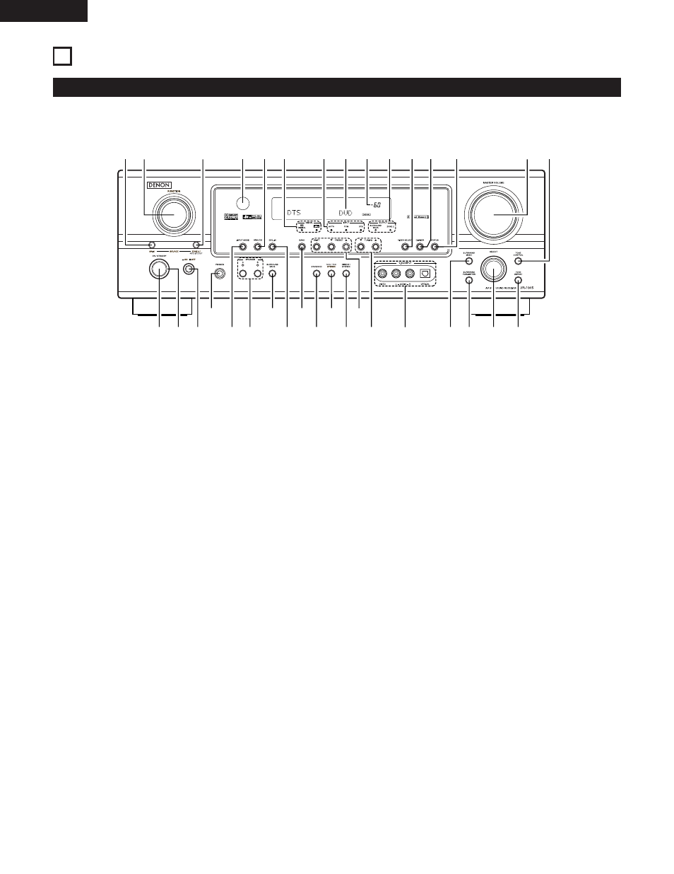
6 PART NAMES AND FUNCTIONS
Front Panel
• For details on the functions of these parts, refer to the pages given in parentheses ( ).
q w
u
e
i
r
y
o
!4
t
!1
@1
@2
@3
@4
@5
@6
@7
@8
@9
!2
!3
!5
!6 !7
!0
!8
@0
!9
#0
#1
#3
#4
#2
q
Power ON/STANDBY switch .......................................(21, 36, 58)
w
Power indicator ..................................................................(21, 36)
e
Power switch .....................................................................(21, 36)
r
Headphones jack (PHONES) ....................................................(40)
t
INPUT MODE button .........................................................(37, 39)
y
SPEAKER A/B buttons .......................................................(36, 61)
u
SURROUND BACK button .......................................................(51)
i
EXT. IN button ....................................................................(37, 39)
o
BAND button ............................................................................(59)
!0
STANDARD button.................................................(45, 47, 49, 51)
!1
5CH/7CH STEREO button ........................................................(55)
!2
DIRECT/STEREO button...........................................................(39)
!3
Preset station buttons ..............................................................(60)
!4
TUNING • (up) / ª (down) buttons ..........................................(59)
!5
V. AUX INPUT terminals.......................................................(5, 12)
!6
SURROUND MODE button......................................................(38)
!7
SURROUND PARAMETER button .....................................(47, 55)
!8
SELECT knob ...............................................................(38, 48, 56)
!9
TONE DEFEAT button ..............................................................(40)
@0
TONE CONTROL button ..........................................................(40)
@1
MASTER VOLUME control ......................................................(38)
@2
STATUS button .........................................................................(41)
@3
DIMMER button .......................................................................(41)
@4
VIDEO SELECT button .............................................................(40)
@5
OUTPUT indicators.............................................................(44, 51)
@6
MASTER VOLUME indicator ....................................................(38)
@7
Display
@8
INPUT mode indicators ............................................................(38)
@9
SIGNAL indicators ....................................................................(38)
#0
ANALOG button .................................................................(37, 39)
#1
Remote control sensor.............................................................(18)
#2
ZONE2/REC SELECT button ..............................................(41, 44)
#3
FUNCTION knob ..........................................................(37, 41, 44)
#4
MAIN button.............................................................................(37)
16
ENGLISH