5 vga + power over utp, Figure 2 – Hall Research UV2-S User Manual
Page 7
5
VGA + Power Over UTP
IMPORTANT
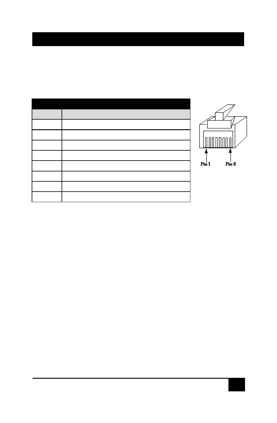
Do not connect this unit to any LAN device such as network cards or hubs
as this may cause damage. Use EIA/TIA 568B standard straight-through
patch wiring as shown below. Do not use crossover cables.
EIA/TIA 568B WIRING STANDARD
PIN
Wire Color
1
White w/ Orange Stripe
2
Orange
3
White w/Green Stripe
4
Blue
5
White w/Blue Stripe
6
Green
7
White w/Brown Stripe
8
Brown
C. At each remote site connect a receiver to the Cat5 cable and plug your
display to its HD15 output connector.
D. Plug a power supply to the System based on the type of the sender used.
In general, you should connect the power supply to the Sender unit. However,
follow these suggestions for best performance.
•
If the sender has more than one RJ45 output then the power supply
must be connected to the sender.
•
If the system is comprised of only one sender and one receiver,
then you can supply power at either the sender or the receiver.
Figure 2