Witch, Ettings for the, Odel – Hall Research UV2-S User Manual
Page 10: Uv1-sl, Vga + power over utp 8, Figure 4
VGA + Power Over UTP
8
This cable ensures that the horizontal alignment of the red, green, and blue
components of the video signal is maintained regardless of the length of the
Cat5 cable. In this cable, the number of twists in each of the 4 pairs in the cable
is the same. If you do not use a Zero Skew cable and feel that the RGB
alignment is off by an unacceptable level, then you can use a Skew Corrector
(Hall Research Model SKU-RGB) at the display device if desired.
•
For Cat5 runs of over 330 ft, you may need to connect a power
supply to the sender as well as the receiver. This is due to the fact
that the resistance of the cable causes a voltage drop from the
sender to the receiver and the voltage level of the power at the
receiver may not be sufficient for proper operation. This extra power
supply must be ordered separately (Model 511-GS569).
•
When using one supply for the system, if the power supply voltage
is not enough due to the length of the Cat5 cable run, the power
LED on some units may start blinking. This signifies that you need
to attach another power supply to the unit that is currently being port
powered.
3.2
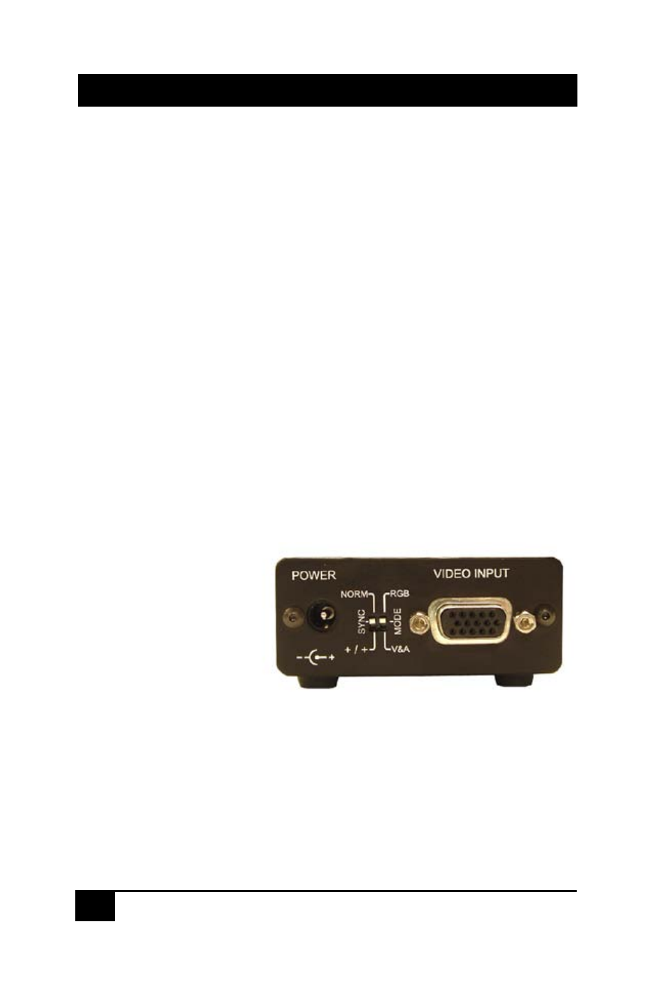
Dip Switch Settings for the Model UV1-SL
The UV1-SL can be
used to transmit
Composite Video and
Stereo Audio as well as
VGA to the receiver.
However since the
Video signals are
terminated differently
than audio, you need to
move the dip switch to the proper position.
Use the Mode Dip Switch to select the video type for transmission.
The Sync Dip Switch is used to change the polarity of sync at the receiver. If
your remote display has trouble positioning the right and left edges of the
screen, then try putting the switch in the +/+ position.
Figure 4