Go Power! GP-SW1000 User Manual
Page 8
GPSW-1000/2000/3000
___________________________________________________________
8
Ground to vehicle chassis using # 8 AWG wire.
d.
Battery terminals:
Connect to 12/24 V battery or other 12/24 V power source. [+] is
positive and [-] is negative. Reverse polarity connection will blow the
internal fuse and may damage inverter permanently.
3.2 GPSW-1000
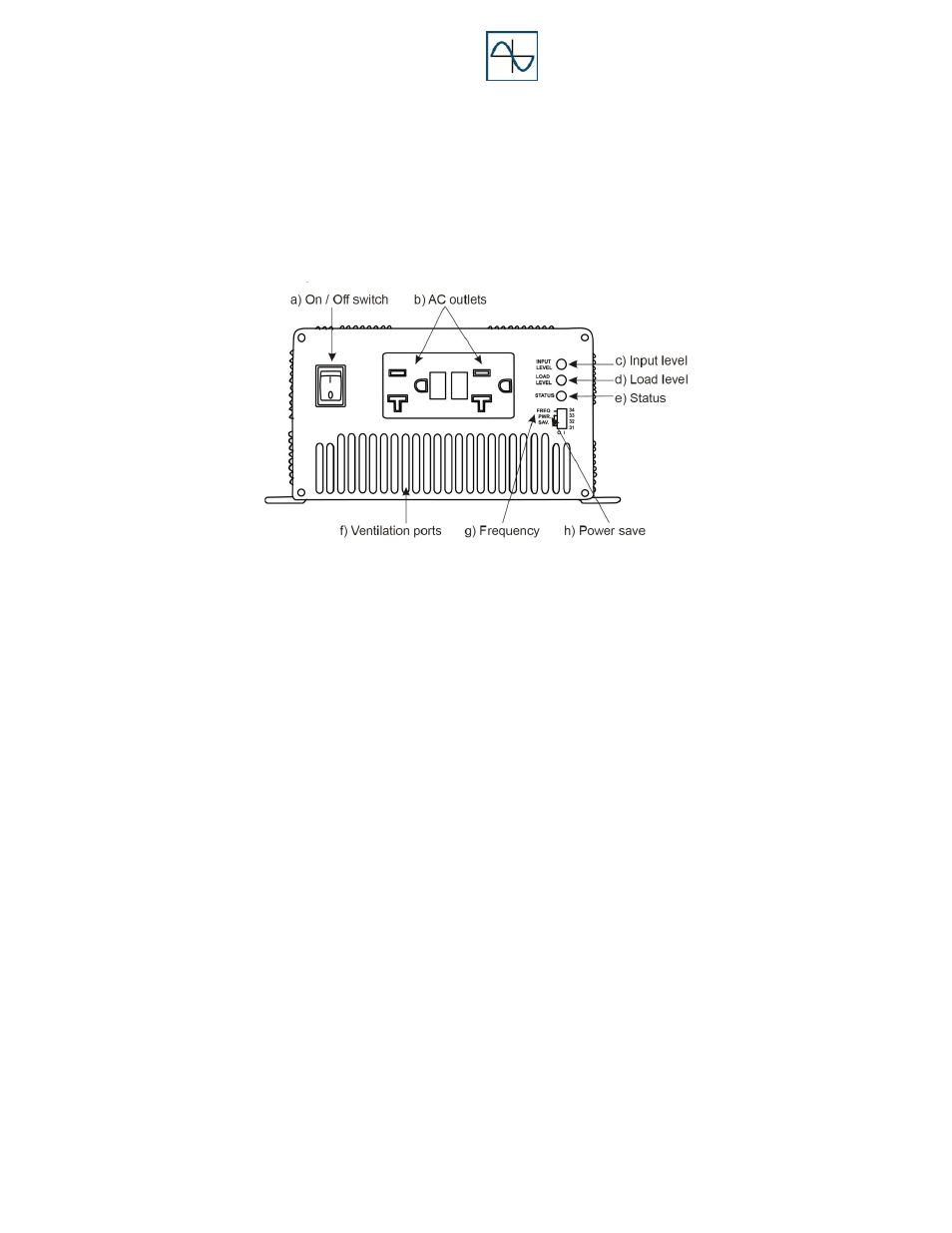
3.2.1 Front View (GPSW-1000)
a.
ON / OFF switch:
Power ON/OFF switch, leave in the OFF position during installation.
Leave in REMOTE position when using optional remote.
b.
AC Outlet: Ground Fault Protected (GFCI)
Outlet sockets available: North America
c.
Input Level:
Displays input voltage. Green indicates normal battery level, yellow
indicates mid to low battery level and red indicates under voltage.
d.
Load Level:
Displays AC load watts. Green indicates normal operation; yellow
indicates mid to high operation and red indicates overload levels.
e.
Status Level:
The LED display indicates the power status of the inverter; see
section 5.0 Operation for more information.