11 electrical connection – Glow-worm Xtrafast 96-120 User Manual
Page 17
17
2000221595
11 Electrical Connection
Warning. This boiler must be earthed
The boiler is supplied with a mains lead attached.
Standard colours are Brown - Live, Blue - Neutral, Green and
Yellow - Earth.
All system components must be of an approved type.
Electrical components have been tested to meet the equivalent
requirements of the BEAB.
Connection of the whole electrical system and any heating
system controls to the electrical supply must be through a
common isolator.
Isolation should preferably be by a double pole switched fused
spur box having a minimum contact separation of 3 mm on each
pole. The fused spur box should be readily accessible and
preferably adjacent to the boiler. It should be identified as to its
use.
A fused three pin plug and shuttered socket outlet may be used
instead of a fused spur box provided that:
a) They are not used in a room containing a fixed bath or shower.
b) Both the plug and socket comply with the current issue of
BS1363.
The mains electrical supply must be maintained at all times in
order to provide domestic hot water.
Do not interrupt the mains supply with a time switch or programmer.
WARNING: ON NO ACCOUNT MUST ANY EXTERNAL
VOLTAGE BE APPLIED TO ANY OF THE TERMINALS ON
THE HEATING CONTROLS CONNECTION PLUG.
Warning: This appliance must be wired in accordance with these
instructions. Any fault arising from incorrect wiring cannot be put
right under the terms of the Glow-worm guarantee.
11.1 External controls
The
XTRAFAST boiler is designed to operate at maximum
efficiency at all times, but will be most efficient and economical
when connected to a room thermostat.
To gain access to the external control connections, unclip side
clips and hinge up control panel cover, see diagram 11.2.
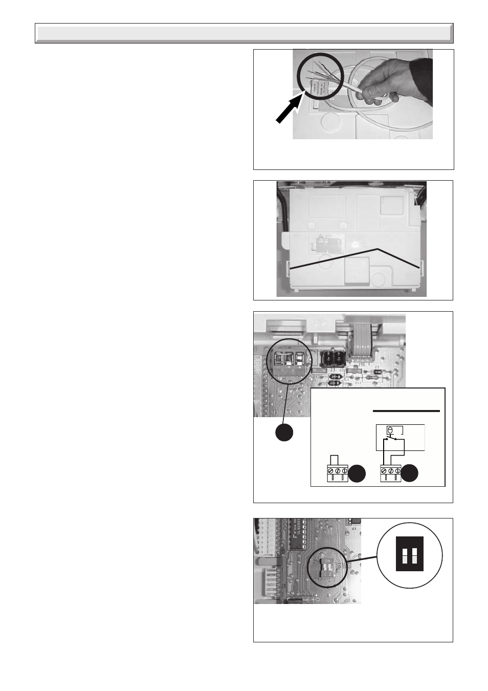
The boiler will work for heating without a room thermostat being
connected provided that the wire link fitted between the two
terminals of the connector (E) is left in place, see diagram 11.3.
Alternatively, a 230V room thermostat can be used but do not
make any connection to the compensating resistor, see diagram
11.3.
ON NO ACCOUNT must any electrical voltage be applied to any
of the terminals of the external controls plug.
Remote Control
A remote control is available for the Xtrafast. Part no. xxxxxx. If
the remote control is fitted the wire link must be in place on
connector (E), and the Switch SW3 must be adjusted, see
diagram 11.4.
11.2 Electrical test
Carry out preliminary electrical system checks as below:
1. Test insulation resistance to earth of mains cables.
2. Test earth continuity and short circuit of all cables.
3. Test the polarity of the mains.
Note: For further information, see the building regulations 1991
- Conservation of Fuel and Power - 1995 edition - appendix G,
Table 4b.
9881
Diagram 11.1
9879
E
Leave link in place for no external controls.
Diagram 11.3
Diagram 11.4
9878
1
2
ON
SW3
TOGGLES
ON
OFF
1 - Remote Control with without
2 - Parameters
open locked
Set 1 & 2 OFF
for normal
operation
The boiler is supplird with a mains lead
attached. Connect this to the electrical supply.
°C
Without room
thermostat
IMPORTANT
With
VOLTAGE FREE
room thermostat
10023
E
E
Diagram 11.2
10036
SIDE CLIPS