6 boiler location, flue and ventilation – Glow-worm Xtrafast 96-120 User Manual
Page 11
11
2000221595
If the appliance has to be stored for any length of time before
installation it should be kept in a safe place where it will not be
a hazard to persons or obstruct any access. Care should be
taken when handling or moving the appliance taking note of the
trucking points on the sides of the carton.
6.1 Clearances
The position of the boiler must be such that there is adequate
space for servicing.
The recommended clearances are:
20 mm either side of the boiler.
600 mm at the front of the boiler.
300 mm below the boiler.
25 mm above the flue elbow.
Note: The boiler must be mounted on a flat wall which is
sufficiently robust to take its weight when full, that is, ** kg. If in
doubt, expert advice should be obtained. In the event of the wall
being found not suitable.
Note: It is permissible to install the boiler with smaller clearances
than those quoted above PROVIDING that adequate
consideration is given for Servicing/Repairs at a later date. If
any doubt exists, contact the Glow-worm Technical Helpline
01773 828100.
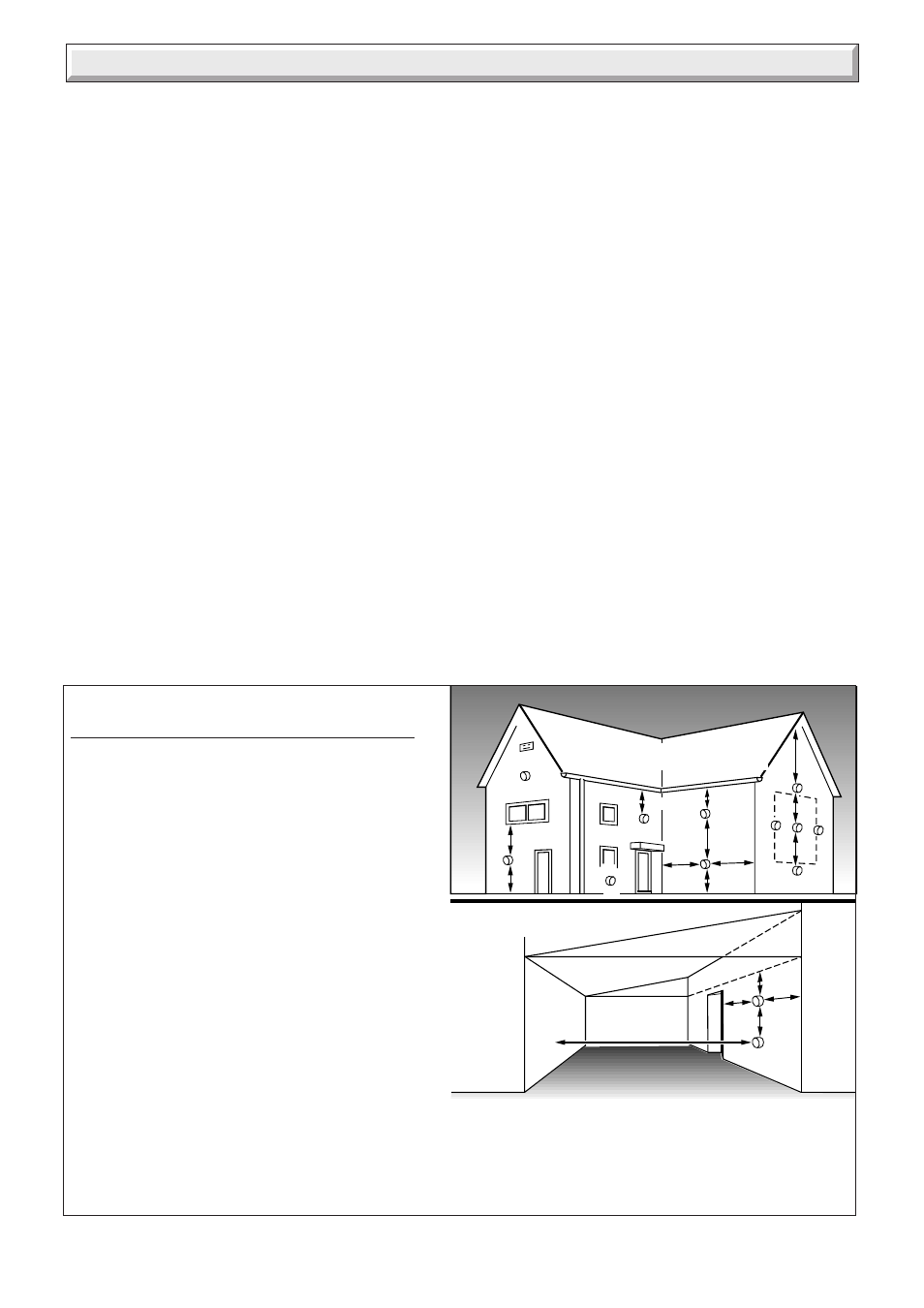
The minimum acceptable spacings from the terminal to
obstructions and ventilation openings are shown in diagram
6.1.
The boiler must be installed so that the terminal is exposed to
the external air.
Should any doubt exist as to the permissible position of the
terminal, contact the Glow-worm Technical Helpline 01773
828100.
6 Boiler Location, Flue and Ventilation
6.2 Terminal guard
A terminal guard is required if persons could come into contact
with the terminal or the terminal could be sublject to damage.
If a terminal guard is required, it must be positioned to provide
a minimum of 50mm clearance from any part of the terminal and
to be central over the terminal.
Teminal guard type K3 supplied by:
Tower flue components Ltd.
Morley road
Tonbridge
Kent
TN9 1RA
6.3 Flue options
There are various flue systems to choose from as follows:
Standard horizontal flue pack.
Standard horizontal extended flue pack.
Vertical flue pack.
Twin flue pack.
Extentions, 90
°
and 45
°
bends.
Flue options and accessories.
For detailed information refer to flue guide Part No. 223278.
6.4 Cupboard or compartment ventilation
The boiler can be fitted in a cupboard or compartment without
the need for permanent ventilation.
A
A
F
G
E
A
G
G
G
B,C
B,C
F
F
K
K
K
C
G
L
L
UNDER CAR PORT etc.
H,I
J
D
F
K
Diagram 6.1
2816
MINIMUM SITING DIMENSIONS FOR THE
POSITIONING OF FLUE TERMINALS
MM
A DIRECTLY BELOW, ABOVE OR
HORIZONTALLY TO AN OPENING, AIR
BRICK, OPENING WINDOWS, AIR VENT, OR
ANY OTHER VENTILATION OPENING
300
B BELOW GUTTER, DRAIN/SOIL PIPE
75
C BELOW EAVES
200
D BELOW A BALCONY OR CAR PORT
300
E FROM VERTICAL DRAIN PIPES AND
SOIL PIPES
300
F FROM INTERNAL CORNERS AND
EXTERNAL CORNERS
300
G ABOVE ADJACENT GROUND OR
BALCONY LEVEL
300
H FROM SURFACE FACING THE
TERMINAL
600
I
FACING TERMINALS
1200
J FROM OPENING (DOOR/WINDOW)
IN CAR PORT INTO DWELLING
1200
K VERTICAL FROM A TERMINAL
1500
L HORIZONTALLY FROM A TERMINAL 600