8 piping system installation – Glow-worm Xtrafast 96-120 User Manual
Page 13
13
2000221595
Sch 173a
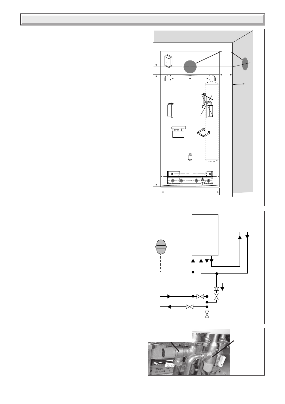
Diagram 8.2
Flow
control valve
Drain point
Filling device
Bypass
valve
Domestic
water
Heating
circuit
Return
Additional
expansion
vessel
(if required)
Boiler
Hot
Cold supply
9684
Diagram 8.1
105
234
20
65
890
470 (96)
552 (120)
8.5 Cutting the flue hole
• Making allowance for the slope of the flue, cut hole in external
wall, preferably using a core drill. For installations with internal
and external access use a 105 mm diameter core drill.
For installations with internal access only use a 125 mm
diameter core drill.
8.6 Important
When cutting the flue hole and when extending the flue centre
line to a side wall, remember that the flue system must have a
fall of about 35 mm per metre of flue DOWNWARD towards the
terminal. There must NEVER be a downward incline towards
the boiler.
8.6 Terminal position
The minimum acceptable spacings from the terminal to
obstructions and ventilation openings are shown in diagram
6.1.
The boiler must be installed so that the terminal is exposed to
the external air.
Should any doubt exist as to the permissible position of the
terminal, contact the Glow-worm Technical Helpline 01773
828100.
8.7 Water connection
Connect the system pipework to the copper connections on the
fixing jig observing the correct flow and return format as shown
in diagram 8.2. Do not subject the isolating valves to heat.
8.8 Heating safety valve and domestic safety
valve discharge, refer to diagram 8.3.
Tee the domestic safety valve outlet pipe to the heating safety
valve outlet pipe and extend horizontally to the outside wall.
WARNING. It must not discharge above an entrance or window
or any type of public access area.
Connect the safety valve discharge pipe to the outlets of both
the heating safety valve and the domestic water safety valve,
the discharge must be extended using not less than 15mm.
pipe, to discharge in a visible position outside the building,
facing downward preferably over a drain.
The pipe must have a continuous fall and be routed to a position
so that any discharge of water, possibly boiling or steam, cannot
create any danger to persons, damage to property or external
electrical components and wiring. Tighten all pipe connection
joints.
8.9 Gas connection
• The supply from the governed gas meter must be of adequate
size to provide a constant inlet working pressure of 20 mbar (8
in w.g.).
To avoid low gas pressure problems, it is recommended that the
gas supply is connected using 22 mm pipe.
• On completion, the gas installation must be tested using the
pressure drop method and purged in accordance with the
current issue of BS6891.
8.10 Gas Safety (Installation and use)
Regulations
In your interests and that of gas safety, it is the law that ALL gas
appliances are installed and serviced by a competent person in
accordance with the above regulations.
8 Piping System Installation
Diagram 8.3
DOMESTIC
SAFETY
VALVE
(10bar)
HEATING SAFETY
VALVE 3 bar)