12 replacement of parts – Glow-worm Ultimate 100FF User Manual
Page 31
31
221966B
NOTE: Replacement of parts must only be carried out by a
competent person.
Before replacing any parts isolate the boiler from the electrical
supply and turn the gas supply off at the gas service cock,
indicator slot to be vertical.
Unless stated otherwise, all parts are replaced in the reverse
order to removal.
After replacing any parts always test for gas soundness and if
necessary carryout functional check of controls.
12.1 Access
Gain access as Section 10.1.
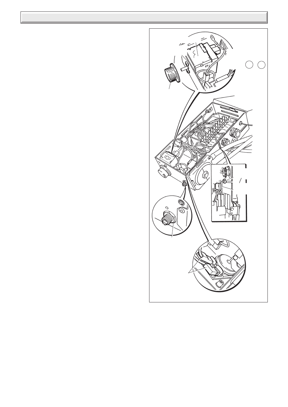
12.2 Control Thermostat - diagram 12.1 and
12.2
Remove and support the electrical control box, refer to Section
7.1.
Remove the control knob. Remove the electrical connections
from the control thermostat body.
Release the control thermostat body be unscrewing the two
screws and shakeproof washers in the front of the control box.
Remove the split pin and withdraw the thermostat phial from its
pocket. Release the capillary from the base and the plastic
retaining clip then remove it from the split grommet. Release the
capillary from its clips. Remove the thermostat complete from
the boiler.
Reassembly NOTE: When refitting the thermostat make sure
that the thermostat phial is covered with heat sink compound
then fully inserted into the phial pocket and that the capillary is
within the gland seal, see diagram 12.2. Remake the electrical
connections. There must be no kinks or sharp bends in the
capillary.
12.3 Overheat Cutoff Device - diagram 12.1,
12.2 and 12.2A
Remove and support the electrical control box, refer to Section
7.1.
Remove the overheat cutoff electrical connections.
Disconnect the air pressure switch plug from the PCB.
Remove the locking nut from the overheat cutoff.
Release the capillary from the retaining clips then remove it
from the split grommet.
Remove the split pin and then the phial.
When refitting use the heat sink compound supplied.
12 Replacement of Parts
Diagram 12.1
ELECTRICAL
CONNECTIONS
YELLOW C &
NC
CONTROL
THERMOSTAT
SHAKEPROOF
WASHERS AND
SCREWS
CONTROL
KNOB
RETAINING
CLIP
SPLIT
GROMMET
LOCKNUT
ELECTRICAL
CONNECTIONS
9076