11 fault finding – Glow-worm Ultimate 100FF User Manual
Page 30
30
221966B
11 Fault Finding
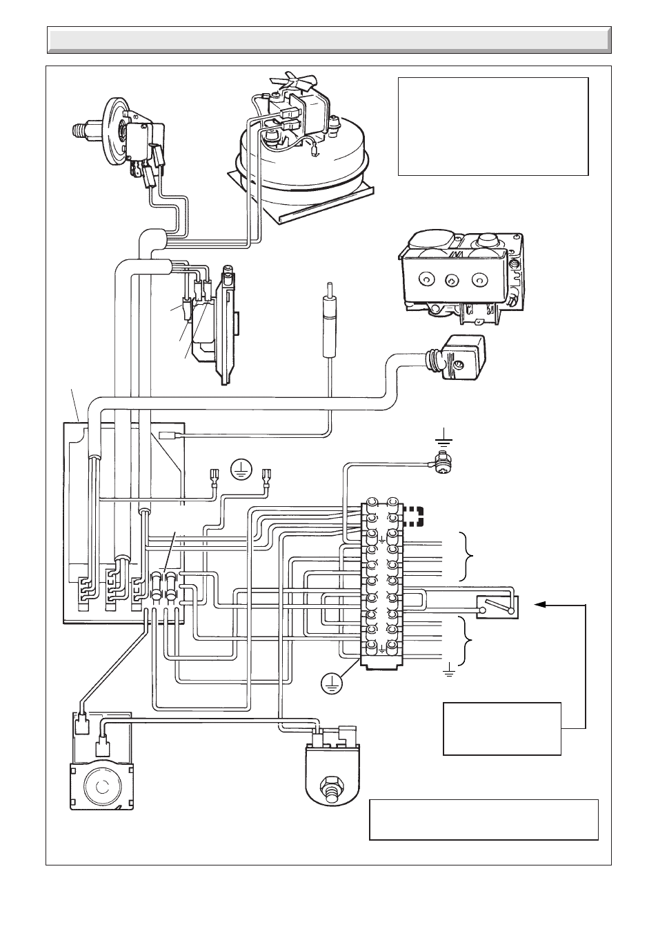
Diagram 11.5
SWITCH CONTROL,
TIME SWITCH,
PROGRAMMER ETC.
(if fitted)
✽
Remove red link between 9 and SL when fitting
a time control etc (If no switch is fitted, link
will make the circulation pump run constantly)
b
r
r
y
AIR
PRESSURE
SWITCH
WATER
PRESSURE
SWITCH
MULTI-FUNCTIONAL
CONTROL
FAN
PLUG
ELECTRODE
SEQUENCE
BOARD
CHASSIS EARTH
g/y
p
b
br
CHASSIS
EARTH
g/y
p
or
b
w
y
y
CONTROL
THERMOSTAT
OVERHEAT
CUTOFF
br
L
N
E
N
L
E
b
b
br
g/y
br
C
NC
g/y
w
230~50Hz
PERMANENT
MAINS
SUPPLY
FUSED
AT 3-AMP
CIRCULATION
PUMP
w
FUSES F1 &
F2 (F1A)
K2
K1
PN
SL
P
9
N
L
NOTE:-
Bridge out Water Pressure Switch
between K1 & K2 if using open vented
system
3 PLUGS
✽ See Note
g/y
NC
bk
NO
C
p
g
FULLY PUMPED OPEN VENTED OR
SEALED WATER SYSTEM
9075
g
b
-
BLUE
bk
-
BLACK
br
-
BROWN
g/y -
GREEN/
YELLOW
r
-
RED
y
-
YELLOW
w
-
WHITE
p
-
PURPLE
g
-
GREY
KEY
p
g/y
g/y
r