8 commissioning – Glow-worm Ultimate 100FF User Manual
Page 21
21
221966B
Please ensure the "Benchmark" logbook is completed and left
with the user.
8.1 All Systems
Commissioning should be carried out by a competent person
in accordance with the current issue of BS6798.
Do not operate the boiler wthout water.
Make sure that the system has been thoroughly flushed out with
cold water without the pump in place.
Refit the pump, fill the system with water, making sure that all
the air is properly vented from the system and pump.
Before operating the boiler check that all external controls are
calling for heat.
8.2 Sealed Water Systems Only
Flush the whole system with cold water without the pump in
place. Refit the pump and fill until the pressure gauge registers
2.7bar (40lbf/in2). Clear any air locks and check for water
soundness.
Check the operation of the safety valve, by allowing the water
pressure to rise until the valve opens. The valve should open
within +/-0.3bar (+/-4.3lbf/in
2
) of the preset pressure. Where
this is not possible conduct a manual check and test.
Release cold water to initial system design pressure.
The set pointer on the pressure gauge should be set to coincide
with the indicating pointer.
8.3 Initial Lighting and Testing
CAUTION: This work must be carried out by a competent
person, in accordance with the current issue of BS6798.
Make sure that all naked lights and cigarettes are out.
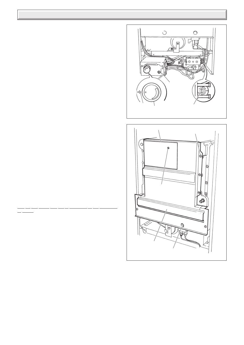
Identify the controls by reference to diagram 8.1.
Check that the boiler is isolated from the electrical supply.
Make sure that the control thermostat is turned to “O” the “Off”
position.
Turn boiler gas service cock “On”.
Test the pilot supply tube and its connection for gas soundness
as follows:
Disconnect the ignition lead from the PCB, see diagram 7.2.
Remove the combustion chamber front, see diagram 8.2.
WARNING: The fan operates on mains voltage, terminals will
become live.
Turn the electrical supply on and check that all remote controls
are calling for heat.
Check that the pump is circulating water through the system.
To complete the test it is necessary to operate the boiler without
its case, but UNDER ALL OTHER CIRCUMSTANCES the
case must be correctly fitted and sealed.
Turn the control thermostat knob fully clockwise and the fan will
work.
NOTE: There will be no sparks at the pilot. Take care and light
the pilot with a match.
Test the pilot supply and connections for gas soundness, using
a suitable leak detection fluid.
Very cold weather may delay the operating sequence.
The pilot rate is preset and must not be adjusted.
The step adjustment screw must not be touched.
The pilot flame length should be as shown in diagram 8.3.
Turn the control thermostat knob to “O” and isolate the boiler
Diagram 8.1
GAS SERVICE COCK
(SHOWN OFF)
Diagram 8.2
SETTING
POINT
OVERHEAT
SAFETY
CUT-OFF
CONTROL
THERMOSTAT
COMBUSTION
CHAMBER
FRONT PANEL
VIEWING
WINDOW
SECURING
SCREW
CLEANING PLATE
SECURING
SCREW (8)
4291
4292
8 Commissioning
from the electrical supply.
Fit the combustion chamber front.
Reconnect the ignition lead to the PCB.
For future reference, stick the self adhesive arrow indicator to
the data label, against the rating that the boiler is going to be set
to. The arrow is in the loose items pack.
Loosen the main burner pressure test point screw and connect
a suitable pressure gauge, see diagram 8.4.
Make sure that any remote controls are calling for heat.
Switch on/connect the electrical supply to the boiler and heating
system, neon 1 will light.