4 flue and appliance preparation – Glow-worm Ultimate 100FF User Manual
Page 14
14
221966B
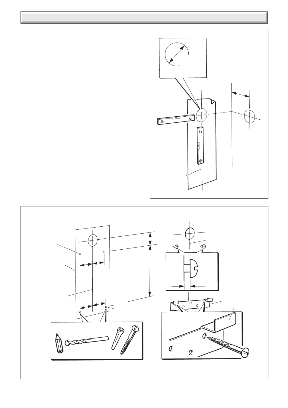
4.4. Rear and Side Flue Application
Take the template from the boiler pack and position it on the
wall, making sure that the minimum clearances are maintained,
see diagram 1.2.
For a rear flue mark the position of the flue as diagram 4.4.
For a side flue, extend the centre line horizontally left or right to
the corner of the adjacent surface where the flue is required to
exit. Mark the position of the centre of the flue and boiler, then
remove template as diagram 4.4.
4.5 Flue Hole Cutting
Having marked out the flue centre cut a hole for the flue using,
preferably, a 120mm minimum core drill.
4.6 Wall Mounting Bracket
Reposition the template, making sure of dimensional alignment
with the flue hole.
Mark the boiler fixing points and mounting bracket position, see
diagram 4.5.
NOTE: the mounting bracket has additional holes to allow for
further fixings should site conditions require it.
Drill holes and plug, to suit No.12x2in woodscrews, fit the
screws allowing sufficient clearance, about 5mm, to accept the
swing brackets, see diagram 4.5.
Secure the mounting bracket to the wall with No.12x2in
woodscrews and plugs, see diagram 4.5.
If the boiler is not to be fitted for some time, cover the hole in the
wall.
Diagram 4.4
120 mm
MINIMUM
HOLE
127mm
SIDE FLUE
FLUE/BOILER
CENTRE LINE
4277
Diagram 4.5
7dia.
TEMPLATE
BOILER
MOUNTING
BRACKET
FLUE/BOILER
CENTRELINE
5mm
3/16in. dia.
PLUG
NO.
12x2in.
MOUNTING
BRACKET FIXING
POINTS
FLUE/BOILER
CENTRELINE
194
172
65.5
749
TOP BOILER
MOUNTING
HOLES
172.5
172.5
4278
4 Flue and Appliance Preparation