4 flue and appliance preparation – Glow-worm Ultimate 100FF User Manual
Page 15
15
221966B
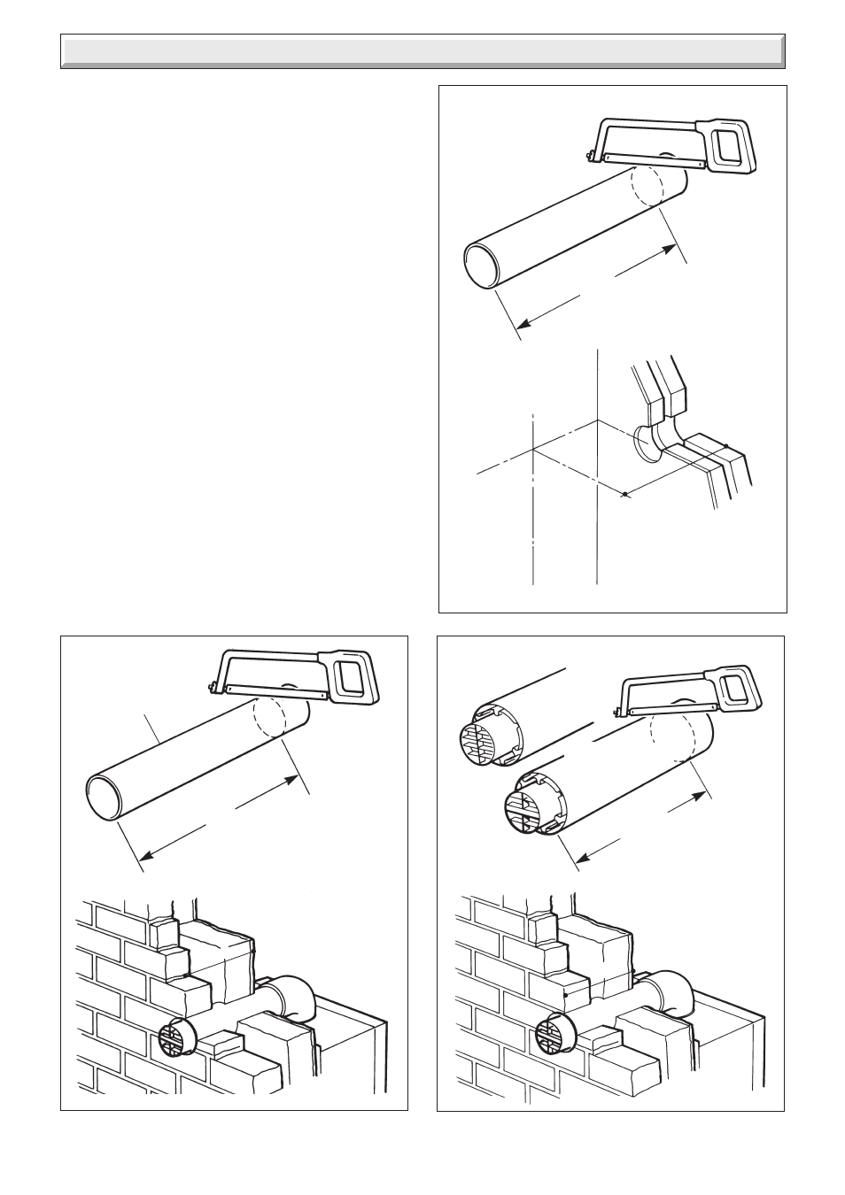
4.7 Flue Length
For a rear flue, measure the distance from the outside wall face
to the boiler mounting wall. Check that the flue length will be
suitable, see diagram 4.2.
For a side flue, measure the distance from the outside wall face
to the boiler centre line. Check that the flue length will be
suitable, see diagram 4.3.
All 2 and 3 metre flue systems are installed in a similar manner
to the standard flue.
4.8 Rear Flue
Mark the air duct/terminal assembly and the flue duct at the
length shown in diagram 4.6 and 4.8 then cut to length, cutting
square and removing any burrs.
NOTE, do not cut the flue duct at the pre-drilled end.
4.9 Side Flue
Mark the air duct/terminal assembly and the flue duct at the
lengths shown in diagram 4.7 and 4.9 then cut to length, cutting
square and removing any burrs.
NOTE, do not cut the flue duct at the pre-drilled end.
4.10 Flue Assembly
Locate the flue duct (drilled end) onto the flue elbow and secure
with the screws supplied in the loose items pack, see diagram
4.10.
Locate the flue duct/elbow into the air duct/terminal spigot and
the air duct/terminal into the flue elbow making sure the correct
alignment of top. Drill the air duct and secure/seal (external
fixing, do not seal) as shown in diagram 4.10.
4.11 Wall Liner
If a wall liner is used, fit foam seal as diagram 4.11.
Diagram 4.6
Diagram 4.7
Diagram 4.8
FLUE
DUCT
Q PLUS 72mm
Q
BOILER
CENTRE
LINE
T MINUS 55mm
Q PLUS 72mm
LONG FLUE
TERMINAL
STANDARD FLUE
TERMINAL
Q
T
6855
6856
6857
4 Flue and Appliance Preparation