9 replacement of parts, 10 fault finding - electrical – Glow-worm Hideaway 80CF User Manual
Page 20
20
221756A
9 Replacement of Parts
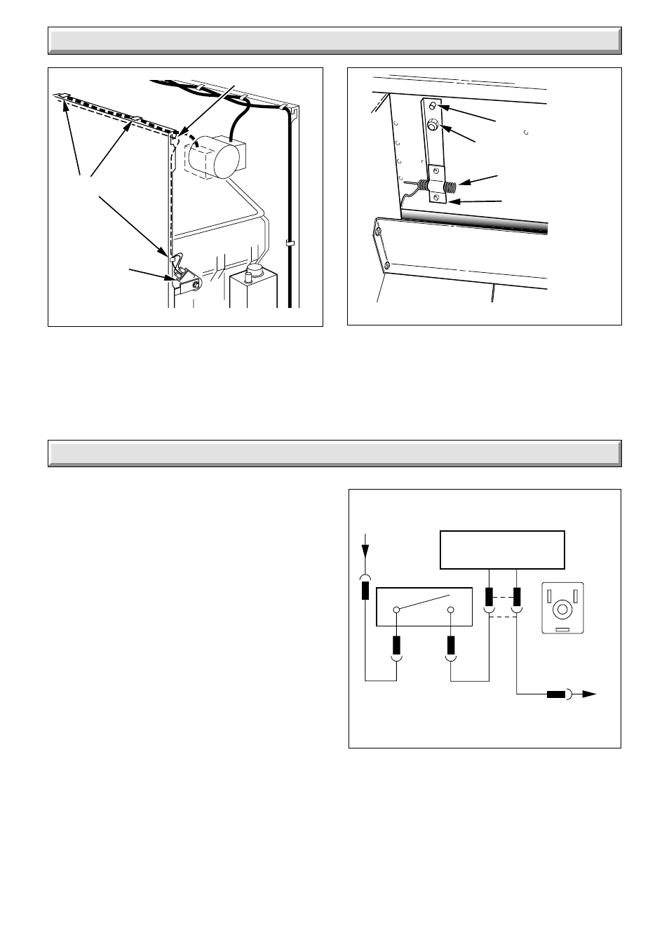
PHIAL ASSEMBLY REMOVAL
Diagram 9.8
LOCATION STUD
SECURING NUT
5042
PHIAL
PHIAL ASSEMBLY
FUNCTIONAL FLOW WIRING
Diagram 10.1
1073
C
N/C
L
N
BLACK
BLUE
BROWN
N
L
GAS VALVE
CONTROL SOLENOID
THERMOSTAT
10 Fault Finding - Electrical
VIEW OF
PLUG WHEN
REMOVED
10.1 Electrical
Refer to functional flow diagram 10.1, electrical fault finding
chart, diagram 10.2 and wiring diagram 9.5.
IMPORTANT. The preliminary electrical system checks
contained in a multimeter instruction book are the first checks
to be carried out during and fault finding procedure. On
completion of the service fault finding task which has required
the breaking and remaking of electrical connections then checks.
earth continuity, polarity and resistance to earth must be
repeated.
10.2 Thermocouple
To test the thermocouple a meter with a range 0 to 30mV is
required together with a thermocouple interrupter test unit
similar to the British Gas Multimeter and interrupter.
Refer to thermocouple fault finding chart, diagram 10.3 and
diagnosis graph, diagram 10.4.
10.3 Pilot and Ignition
Refer to pilot and ignition fault finding chart, see diagram 10.6
and 10.3.
10.4 Flue Blockage Safety Device
If the device operates it indicates there is a problem with the
chimney. Make sure that the air vents are free from obstruction.
Carry out spillage checks as BS5440 Part 1 and put right as
necessary.
8066
FLUE
BLOCKAGE
SAFETY
DEVICE
CAPILLARY REMOVAL
Diagram 9.7
CABLE CLIPS
CAPILLARY