9 replacement of parts – Glow-worm Hideaway 80CF User Manual
Page 18
18
221756A
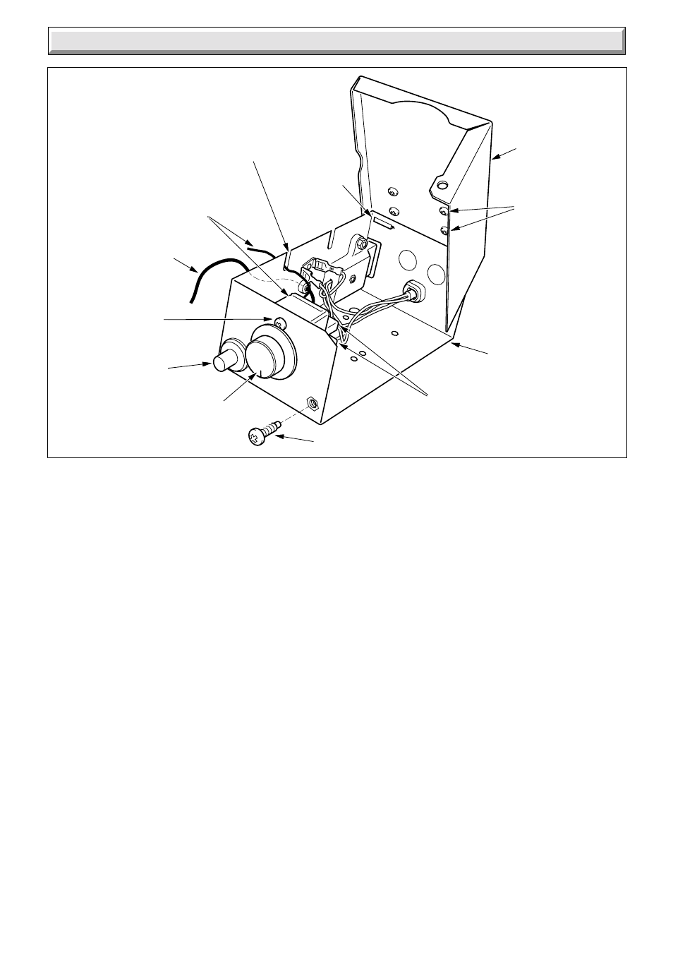
9.7 Boiler Thermostat
Follow the relevant instructions in Section 8.1.
Remove the mains inlet connector by pulling downwards, see
diagram 8.1.
Remove the retaining split pin from the phial pocket then
withdraw the phial and capillary, see diagram 8.2
Pull off the thermostat control knob.
Gain access to inside of the control box by removing the
securing screw located at the top of control box and unhooking
at the bottom, see diagram 9.4.
Remove the two screws which secure the boiler thermostat to
the control box, see diagram 9.4.
Tilt the thermostat so that the electrical connections can be
removed.
Withdraw boiler thermostat from control box complete with
capillary tube and phial.
Refer to diagram 9.5 to connect electrical connectors.
Replace the thermostat phial as the relevant part of Section 8.5.
Make sure that the capillary is positioned so that it passes
through the cut out in the control box, see diagram 9.4.
9 Replacement of Parts
9.5 Spark Electrode
Gain access to the boiler as Section 8.1.
Disconnect the thermocouple nut and withdraw thermocouple
from pilot burner, see diagram 9.2.
Disconnect the nut retaining the spark electrode and remove.
Check that the spark gap is as shown in diagram 7.2.
9.6 Insulation Panels
Gain access to the boiler as Section 8.1.
Remove the burner assembly as the relevant parts of Section
8.2.
Remove the two screws retaining each side insulation panel
within the combustion chamber and remove panel, see diagram
9.3.
Release the rear insulation panel upper clips and lift out panel.
Reassemble in reverse order.
Refit the thermostat phial as the relevant part of Section 8.5.
7995
ELECTRICAL
CONNECTORS
ELECTRICAL
CONTROL BOX
COVER
COVER
SECURING
SCREW (4)
THERMOSTAT
SECURING
SCREW (2)
THERMOSTAT
CONTROL KNOB
PIEZO UNIT
HOOK
IGNITION LEAD
(BLACK END)
CUT-OUT FOR
CAPILLARY
SECURING SCREW
THERMOSTAT
AND CAPILLARY
Diagram 9.4
CONTROL BOX
ELECTRICAL
CONTROL BOX