4 installation – Glow-worm Hideaway 80CF User Manual
Page 10
10
221756A
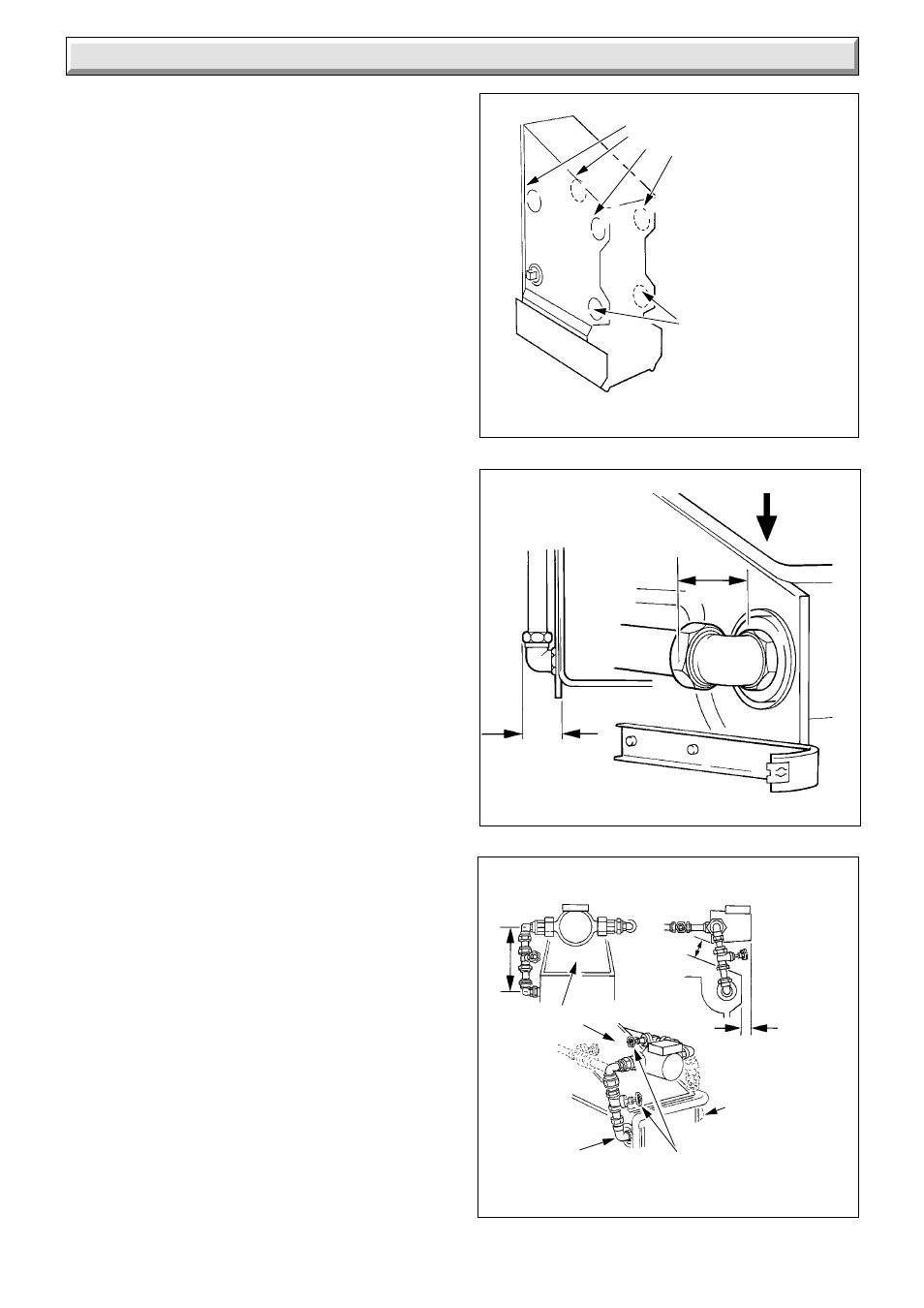
When suitable installation clearances are available, position
the boiler in readiness to connect pipework.
If suitable clearances are not available it will be necessary to
preplumb the gas and water connections before positioning the
boiler.
When the front connections are used it is essential that any
pipework or fittings be assembled as shown in diagram 4.5, that
is, do not stick out more than shown.
Make the water connections to the system pipework.
Make the gas connection to gas supply at the union gas service
cock. Test the complete gas installation for soundness and
purge in accordance with the current issue of BS6891.
4.6 Pump within Boiler Casing
If the pump is to be fitted inside the boiler casing connect it as
shown to either of the upper front flow connections, see diagram
4.6.
There must be sufficient clearance “X” between the pump body
and the flueway cleaning door to allow removal of the door.
Dependent upon the type of pump used, the flow pipe
arrangements and pump may require titling backwards to clear
the casing door.
4.7 Flue Connection
The flue should be 125mm (5in) nominal diameter, refer to
Section 3 and diagram 1.1.
Fix and seal the flue to the hood in accordance with normal
practice.
Diagram 4.6
Diagram 4.4
WATER CONNECTIONS FULLY
PUMPED SYSTEMS
PUMP CLEARANCES
0874
ALTERNATIVE FLOW
POSITIONS
ALTERNATIVE
RETURN
POSITIONS
With distributor
tube (not shown)
Clearance 'X' must be left to enable cleaning
door removal and boiler servicing
'X'
FLUEWAY
CLEANING
DOOR
ALTERNATIVE
R.H. FLOW
CONNECTION
ISOLATING
VALVES
L.H. FLOW
CONNECTION
175
(7)
35 (1
3
/
8
)
0875
Diagram 4.5
PIPEWORK
CASING CLEARANCES
VIEW ON ARROW 'A'
1524
'A'
57 MAX.
(2
1
/
4
in.)
BOILER
57 MAX.
(2
1
/
4
in.)
4 Installation