9 replacement of parts – Glow-worm Hideaway 80CF User Manual
Page 19
19
221756A
9 Replacement of Parts
9.8 Piezo Unit
Pull door forward at the top to disengage the studs and lift to
release from slots, see diagram 7.3.
Remove mains inlet connector by pulling downwards, see
diagram 8.1.
Open the control box by removing securing screw and support
on the hook on the bottom of the control box cover, see diagram
9.4.
Disconnect the ignition lead at the piezo unit.
Note: To ease the removal of the piezo unit it is advisable to
temporarily remove the boiler thermostat from the control box.
Depress the retaining tabs and remove the Piezo unit.
9.9 Ignition Lead
Gain access to the boiler as Section 8.1.
Disconnect the ignition lead at the piezo unit, see diagram 9.4,
and section 9.8.
Remove the lint arrester gauze as the relevant parts of Section
8.3.
Disconnect the ignition lead at the spark electrode, see diagram
9.2.
When reconnecting the lead make sure that the clear end is
fitted to the spark electrode and that the black protective
sleeving is in place before fitting the lint arrester gauze.
9.10 Electrical Control Box
Gain access to the boiler as Section 8.1.
Disconnect the mains inlet connector, see diagram 8.1.
Remove the retaining split pin from the phial pocket then
withdraw phial and capillary, see diagram 8.2.
Disconnect the gas valve plug from the valve, see diagram 9.1.
Release the control box by removing the securing screw located
at the top of control box and unhooking at the bottom, see
diagram 9.4.
Pull the ignition lead off piezo unit, see diagram 9.4.
When refitting control box make sure the thermostat capillary is
positioned so that it passes through the cut out in the control
box, see diagram 9.4.
Refit thermostat phial, refer to Section 8.5.
FLUE
BLOCKAGE
SAFETY DEVICE
SECURING
LOCKNUT
ELECTRICAL
CONNECTIONS
ELECTRICAL CONNECTIONS
Diagram 9.6
8056
CAPILLARY
9.11 Flue Blockage Safety Device
Gain access to the boiler as Section 8.1.
Remove the electrical connections from the safety device body.
Remove the capillary from cable clips, see diagram 9.7.
To remove the phial assembly, first gain access through flue
cleaning door as Section 8.1.
Unscrew securing nut and withdraw the phial assembly from the
flue, see diagram 9.8.
Remove the locknut securing the Flue Blockage Safety Device
to the bracket and withdraw the Flue Blockage Safety Device
and phial assembly, see diagram 9.6.
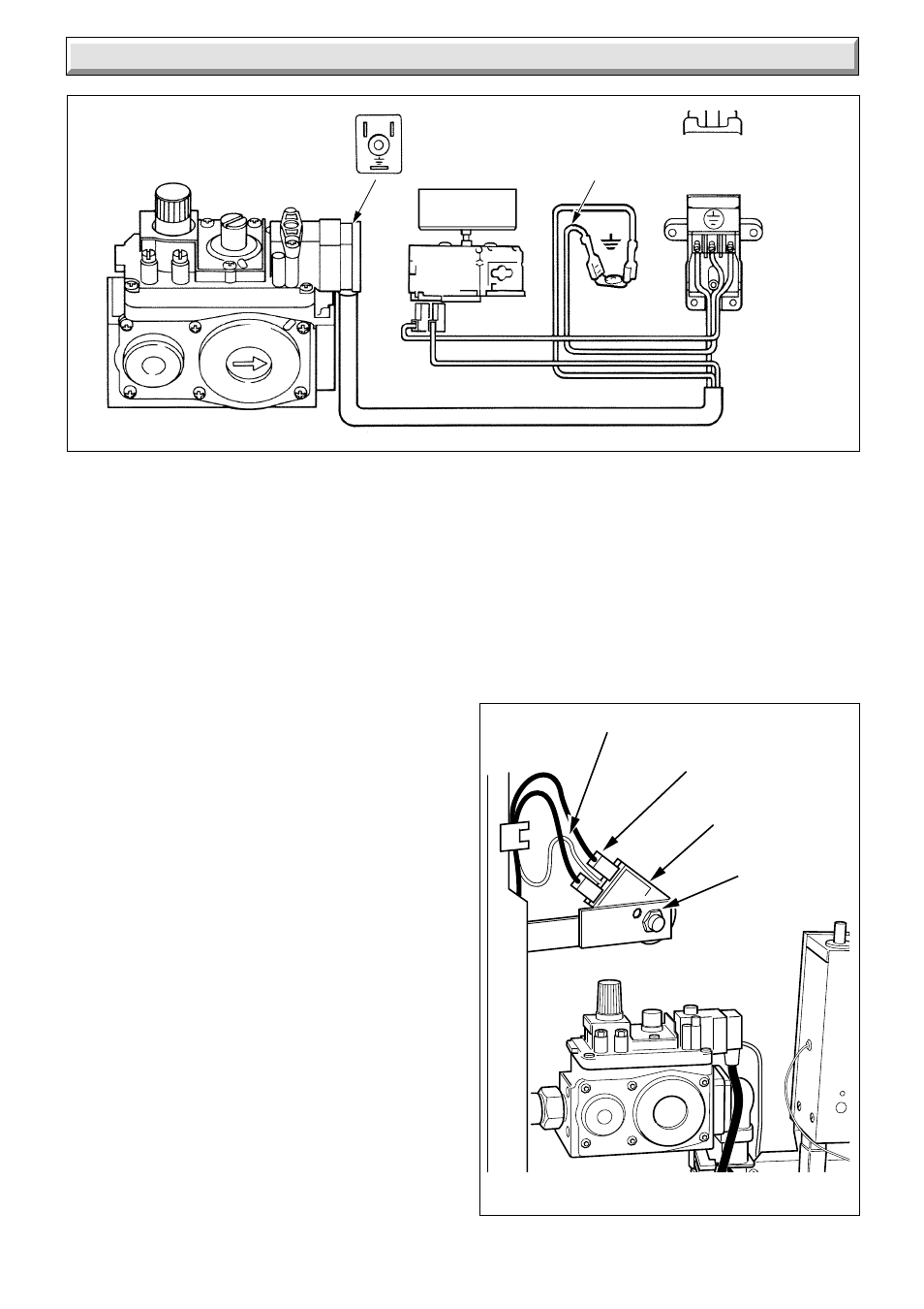
Diagram 9.5
CONTROL BOX AND GAS VALVE WIRING
8079
CHASSIS
EARTH
230V~ 50Hz
MAINS SUPPLY
FUSED AT 3A
BLUE
BLACK
GREEN / YELLOW
BROWN
C
THERMOSTAT
GAS VALVE
N
E
N
L
VIEW OF PLUG
WHEN REMOVED
L
GREEN/
YELLOW
N/C