6 electrical wiring – Glow-worm Hideaway 80CF User Manual
Page 12
12
221756A
AP
AP
P
P
CB
CB
CB
CB
230
(9)
25
(1)
230
(9)
230
(9)
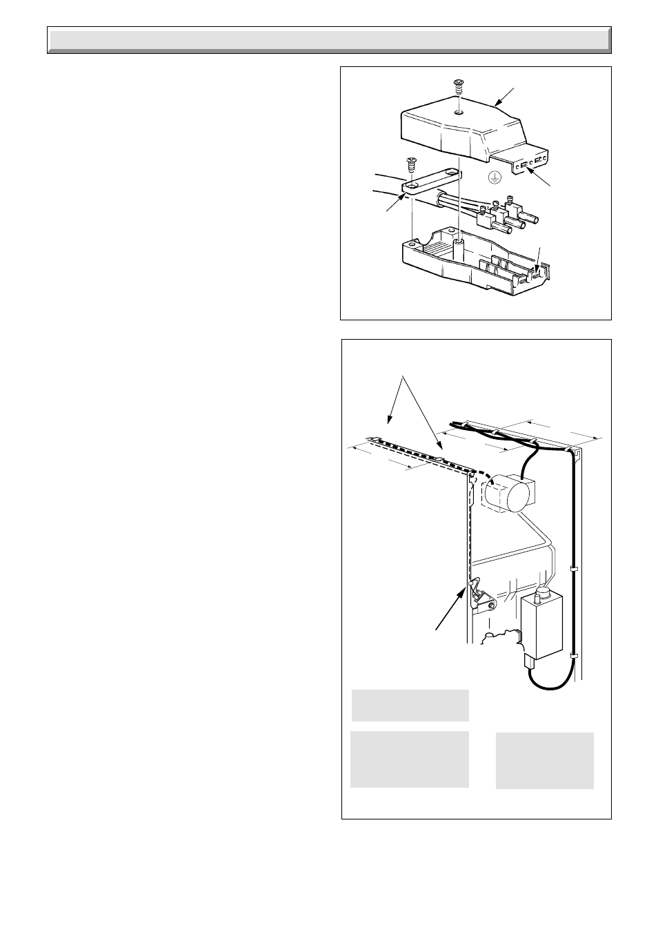
6.1 Control Box Cable Connection
Remove the screw and cover from the mains inlet connector,
see diagram 6.1.
Using heat resistant flexible cable of suitable length and rating,
as Section 1.6, connect the cable to the terminals in the
connector. Secure the outer sheathing with the clamp.
Engage slots and lugs, replace connector cover and secure
with screw.
Connect mains inlet connector to the control box and use three
of the cable clips, supplied loose, pushed on to the edge of the
left hand panel in positions “CB” as shown in diagram 6.2 to
make sure that the cable does not touch any hot surfaces.
6.2 Circulation Pump Cable Connection
Heat resistant cable with a rating as stated in Section 1.6 must
be used for all wiring near the boiler, including the pump, if within
the boiler casing.
Support the pump cable away from hot surfaces if within the
boiler casing by pushing two cable clips, supplied loose, on to
the top edge of one side casing, as shown as “P” or “AP” in
diagram 6.2.
6.3 Flue Blockage Safety Device - Capillary
and Interrupter Electrical Leads
For transit the capillary is taped to the side of the boiler.
Remove tape and place capillary into cable clips provided, see
diagram 6.2.
Note: Capillary must not touch the heat exchanger side.
Secure the interrupter electrical leads so as not to strain them,
see diagram 6.2.
6.4 System Controls
The electrical installation must be in accordance with the
current issue of BS7671.
The electrical isolator must isolate both the boiler and system
controls.
6.5 Testing
Checks to ensure electrical safety should be carried out by a
competent person.
In the event of an electrical fault after installation of the boiler,
preliminary system checks must be carried out, that is, earth
continuity, polarity and resistance to earth as described in a
multimeter instruction book.
6 Electrical Wiring
8064
CABLE CLIP POSITIONS
Diagram 6.2
Fit 4 control
box feed cable
clips at positions
CB
Alternative pump
cable clips (if feed is
on the left hand side)
at positions AP
Fit 2 pump cable
clips at positions P
SAFETY DEVICE CAPILLARY
CLIP POSITION
CAPILLARY AND
INTERRUPTER
ELECTRICAL LEADS CLIP
MAINS INLET CONNECTOR
Diagram 6.1
0878
N E
L
COVER
CABLE
CLAMP
LUGS
SLOTS