8 servicing – Glow-worm Hideaway 80CF User Manual
Page 15
15
221756A
8 Servicing
Servicing must be carried out by a competent person.
Before starting any servicing, turn off the gas and electrical
supply to the boiler.
Always test for gas soundness after completing any servicing
or replacement of gas carrying components.
8.1 Gain Access to Boiler
Pull door forwards at the top to disengage studs and lift to
release from the slots, see diagram 7.3.
Lift the plinth front up and forwards to withdraw, see diagram
7.3.
If the top casing is removed, care must be taken not to damage
or lose any plastic pegs when refitting, see Section 5.3.
8.2 Boiler Flueways
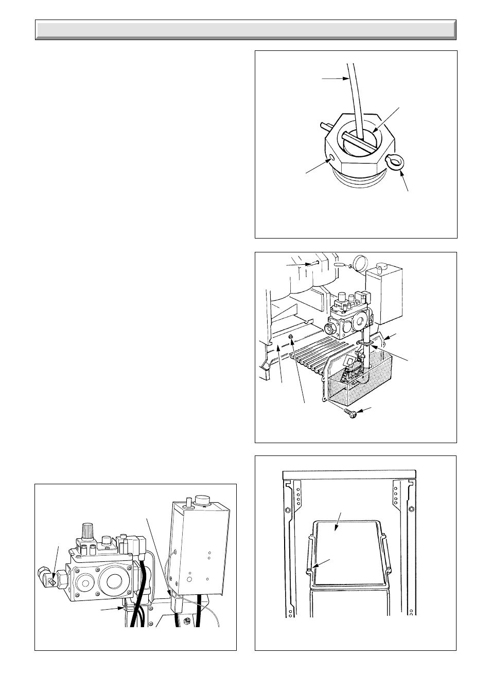
Unscrew the union nut securing the gas service cock to the gas
valve, see diagram 8.1.
Remove the mains inlet connector by pulling downwards, see
diagram 8.1.
Remove electrical connections from the interupter, see diagram
8.1.
Remove the retaining split pin from the phial pocket then
withdraw the phial and capillary, see diagram 8.2.
Remove the four screws retaining the combustion chamber
cover and burner assembly, see diagram 8.3.
Ease the gas service cock away from the gas valve and unhook
the pipe support bracket from the tie bar to enable the assembly
of cover, control box, gas valve and burner to be withdrawn
forward.
Remove graphite coated nuts to release baffle tray, remove
from combustion chamber taking care not to damage the
insulation material.
Remove self-tapping screws which retain the flueway cleaning
door and lift door clear, see diagram 8.4.
Remove flueway baffles, see diagram 8.7.
Place a sheet of paper in the combustion chamber to catch any
flue debris.
Access for flueway cleaning is made through the flueway
cleaning and combustion chamber openings.
Thoroughly clean boiler flueways and fins from the top and
bottom with a suitable stiff brush. Remove any debris from the
base of the combustion chamber.
Check that the flueways are clear, view with the aid of a mirror
or reflector.
ACCESS TO FLUEWAY
Diagram 8.4
0908
FLUEWAY
CLEANING
DOOR
SELF-
TAPPING
SCREW (4)
Diagram 8.2
SECURING THE
THERMOSTAT PHIAL
1870
LOCATION
WASHER
PHIAL
POCKET
RETAINING
SPLIT PIN
THERMOSTAT
CAPILLARY
ACCESS FOR SERVICING
Diagram 8.3
7993
SECURING
SCREW (4)
GRAPHITE
COATED NUT
BAFFLE
TRAY
COMBUSTION
CHAMBER
COVER
PIPE
SUPPORT
BRACKET
TIE
BAR
Diagram 8.1
ISOLATION OF
GAS AND ELECTRICITY
7992
MAINS INLET
CONNECTOR
(pull downwards)
GAS
SERVICE
COCK
(turn off)
(shown
closed)
ELECTRICAL
CONNECTIONS