9 replacement of parts – Glow-worm Hideaway 80CF User Manual
Page 17
17
221756A
9 Replacement of Parts
Before removing or replacing any parts turn off the gas and
electrical supplies to the boiler.
Always test for gas soundness after replacing any gas carrying
components.
Replacement of parts is in the reverse order to removal unless
stated otherwise.
9.1 Gas Valve
Gain access to the boiler as Section 8.1.
Refer to the relevant parts of Section 8.2.
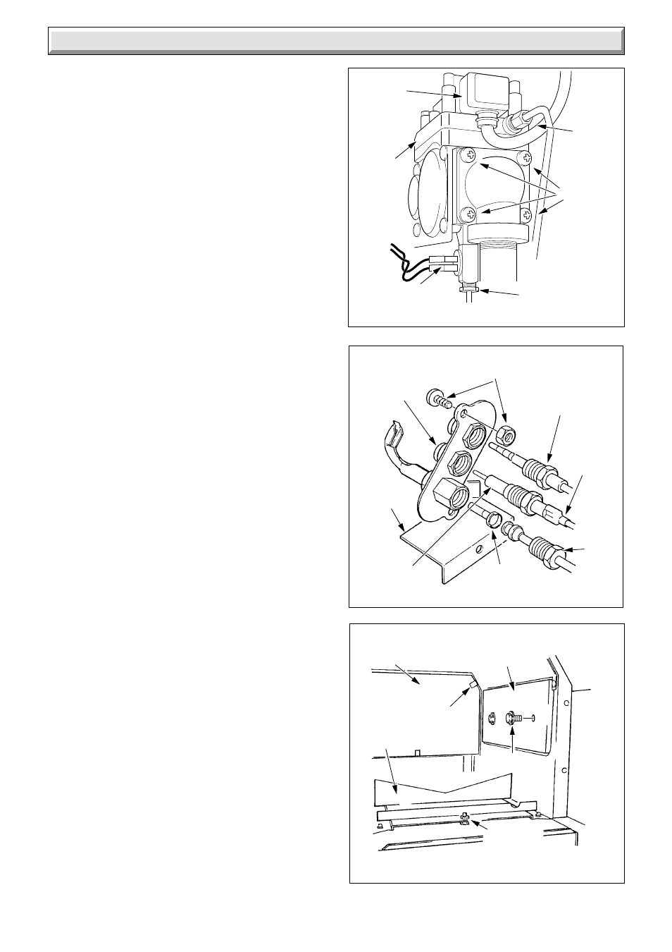
Disconnect the thermocouple nut, interrupter electrical
connections and pilot tube connections at the gas valve, see
diagram 9.1.
Support the valve and remove the four right hand flange screws
to disconnect the gas valve from the burner supply pipe.
Ease the gas service cock union out and remove the valve
taking care not to damage the “O” ring seal at the flange.
Inspect the condition of the “O” ring seal and renew if necessary.
Remove the union half and refit into replacement valve on the
inlet, left hand side. Use a little jointing compound, on external
thread only, to ensure gas soundness.
It will be necessary to purge air from the gas supply, relighting
should be carried out as Section 7.2.
9.2 Injectors
Gain access to the boiler as Section 8.1.
Refer to the relevant parts of Section 8.2 and 8.3.
Unscrew the injector from the manifold and renew as necessary.
When replacing the injector use a little jointing compound, on the
external thread only, to ensure gas soundness.
Replace thermostat phial.
9.3 Thermocouple
Gain access to boiler as Section 8.1.
Remove the lint arrester as Section 8.3.
Disconnect the thermocouple by unscrewing nuts at the gas
valve and pilot burner, see diagram 9.1 and 9.2. Withdraw the
thermocouple.
Replace the lint arrester as Section 8.3.
9.4 Pilot Burner
Gain access to boiler as Section 8.1.
Remove cover and burner controls assembly, as relevant parts
of Section 8.2.
Remove lint arrester as Section 8.3.
Disconnect the ignition lead at the electrode, see diagram 9.2.
Disconnect the thermocouple nut at the pilot burner.
Disconnect the pilot tube nut, ease out the tube and injector
which is hooked on to the pilot tube.
Remove the nut retaining the spark electrode and remove.
Remove the two screws and nuts securing the pilot burner and
shield to the combustion chamber cover.
Reassemble in the reverse order, hooking pilot injector over
pilot tube olive when refitting.
Replace thermostat phial, Section 8.5.
Replace lint arrester, Section 8.3.
Check that the pilot flame length is as shown in diagram 7.2.
INSULATION PANELS
Diagram 9.3
SIDE
INSULATION
PANEL
REAR
INSULATION
PANEL
6305
GRAPHITE
COATED
NUT
SCREW
CLIP
BAFFLE
TRAY
PILOT ASSEMBLY
Diagram 9.2
2038
PILOT
TUBE
NUT
SPARK
ELECTRODE
IGNITION
LEAD
(CLEAR
END)
PILOT
INJECTOR
PILOT
BURNER
PILOT
SHIELD
SECURING SCREW (2)
AND NUT (2)
THERMOCOUPLE
NUT
8058
GAS
VALVE
PLUG
PILOT
TUBE
NUT
THERMOCOUPLE
NUT
INTERRUPTER
CONNECTIONS
GAS
OUTLET
FLANGE
SCREW
(4)
Diagram 9.1
REMOVAL OF GAS VALVE
GAS
VALVE