8 servicing – Glow-worm Hideaway 80CF User Manual
Page 16
16
221756A
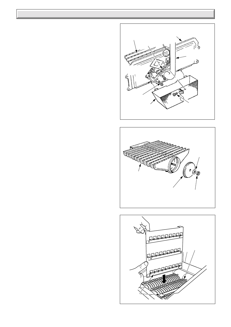
REMOVAL OF BURNER
8 Servicing
Diagram 8.5
BURNER SERVICING
Diagram 8.6
1153
8.3 Burners and Injectors
Follow instructions to remove the cover, burner and controls
assembly as described in Section 8.2.
Remove the screw securing the lint arrester gauze to combustion
chamber cover. Remove arrester by lifting slightly and
withdrawing forwards to clear burner supply pipe and
thermocouple etc., see diagram 8.5.
Remove the four burner securing nuts from the flange of the
burner supply pipe.
Remove the burner from the cover/supply pipe flange.
Remove the securing nut, washer and burner end cap from
burner, see diagram 8.6.
Clean the burner parts and lint arrester with a vacuum cleaner.
Check that the main burner injector is not damaged or blocked.
Clean or renew as necessary, do not clean with a wire or sharp
instrument. Refer to Section 9.2 and diagram 8.5.
When replacing the lint arrester locate the two lugs into the slots
on the combustion chamber cover and locate around the feed
pipe etc., then secure with the screw.
8.4 Service Checks
Inspect the thermocouple and pilot burner, clean or renew as
necessary.
Check the condition of the insulation panels in the combustion
chamber. Renew if necessary.
Check the condition of the seals on the flueway cleaning door
and the combustion chamber, renewing if necessary.
8.5 Reassembly
Make sure that the baffle tray is replaced and secured with the
graphite coated nut, previously removed.
Make sure that the thermostat phial is fully inserted into the phial
pocket. Position the location washer behind the retaining split
pin, see diagram 8.2.
8.6 Operational Check
Light the boiler and carry out the operational checks as described
in Sections 7.2 and 7.3.
SECURING
SCREW
LINT
ARRESTER
SECURING
NUT(4)
MAIN
BURNER
INJECTOR
COMBUSTION
CHAMBER
COVER
1147
BURNER
SUPPLY PIPE
BURNER
BODY
BURNER
END CAP
WASHER
SECURING
NUT
Diagram 8.7
6116
BAFFLES
HEAT
EXCHANGERS