Installation – Glow-worm Clearly Solar Cylinders User Manual
Page 23
0020115479_03 - 10/12 - Glow-worm
- 21 -
INSTALLATION
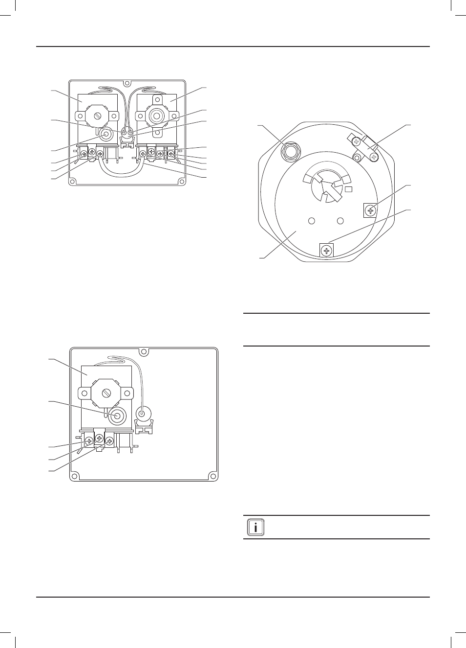
9.7.5
Cylinder thermostat and thermal cut out (TCO)
for the reheating circuit
1
2
3
4
5
6
14
13
12
11
10
7
8
9
Key:
1 Cylinder thermostat
2 Cylinder thermostat temperature sensor
3 lower immersion sleeve
4 Terminal for cylinder thermostat protective earth
5 Cylinder thermostat terminal 1
6 Cylinder thermostat terminal 2
7 Cylinder thermostat terminal C
8 bridge
9 Reheating circuit TCO terminal 2
10 Reheating circuit TCO protective earth terminal
11 Reheating circuit TCO C terminal
12 Reheating circuit TCO reset button
13 Reheating circuit TCO temperature sensor
14 Reheating circuit safety thermostat (TCO)
Disconnect from the mains supply before you remove any of the
underlying component covers.
9.7.6
solar circuit thermal cut out (TCO)
1
2
3
4
5
Key:
1 solar circuit thermal cut-out (TCO)
2 solar circuit TCO reset button
3 solar circuit TCO terminal C
4 solar circuit TCO protective earth terminal
5 solar circuit TCO terminal 2
The live supply to the solar pump MUST be run in series through
terminals 3 and 5 from the solar control to the pump for this to be
operative as the solar TCO.
9.7.7
Connecting up the electric immersion heater
The Glow-worm Flurocyl
2
solar cylinders are fitted with an electric
immersion at the factory.
9.7.8
electrical connection of electric immersion
heater
1
2
3
4
5
4
2
3
1
5
Key
1 Protective earth terminal (Pe)
2 Cable grip
3 Neutral conductor terminal (N)
4 Outer conductor terminal (l)
5 electric immersion heater
e
Without earthing, life-threatening voltage can reach
the piping and water draw-off points.
- Earth the cylinder.
• The electric immersion heater must be earthed.
• Dismantle the electric immersion heater cover.
• Install a separate electrical power supply for the electric
immersion heater in accordance with current IEE regulations
(BS 7671).
- Use heat-resistant cables (H05BN4-F 1.5 mm² 3 core HOFR
sheathed flexible cable) for the cabling of the electric
immersion heater.
- Use the cable grip (2) to firmly secure the supply cable of the
immersion heater.
- Connect the electric immersion heater to the power mains via
double pole isolating switch with a contact separation of at
least 3 mm in both poles.
- Protect the circuit using a 13 A fuse. Mount the cover for the
electric immersion heater.
Only switch the immersion heater on once the cylinder
is completely full.
With the circuit breaker, the electric immersion heater can be
switched on if the reheating device has malfunctioned.