Installation, 9 cylinder installation, 1 cylinder device description – Glow-worm Clearly Solar Cylinders User Manual
Page 15
0020115479_03 - 10/12 - Glow-worm
- 13 -
9 Cylinder installation
9.1
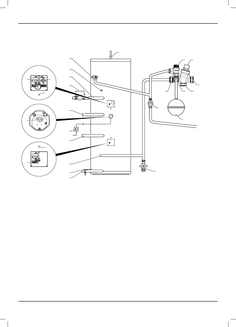
Cylinder device description
15
14
22
20
21
1
13
11
12
16
17
3
19
23
24
25
26
18
2
3
4
5
6
7
9
8
10
Key
1 Hot water connection
2 expansion relief valve (one-way valve, 6.0 bar)
3 Pressure limiting valve (3.5 bar) with line strainer
4 Cold water connection
5 Pressure-controlled cold water connection
6 Connection for hot water expansion vessel
7 Cylinder connection
8 Hot water expansion vessel
9 Tundish
10 Cylinder drain valve (not supplied)
11 Return line (solar circuit)
12 solar collector temperature sensor
13 Cold water pipe
14 solar circuit safety thermostat (TCO), set to 80 °C, to be connected
with the solar pump in order to isolate this heat source
if there is a malfunction in the solar control.
15 solar circuit immersion sleeve (length 70mm dia. 8mm) (TaC 2)
16 supply line (solar circuit)
17 2- pole circuit breaker for electric immersion heater
18 electric immersion heater with thermostat and safety thermostat
(20°C to 65 °C) (length 70mm dia. 8mm)
19 Return line (gas-fired boiler)
20 Reheating circuit immersion sleeve (TaC 1)
21 Reheating circuit safety thermostat, set to 80 °C, to be connected
to the 2-way motorised valve in order to isolate the primary
heat source if a malfunction occurs.
22 Cylinder thermostat (25 °C to 65 °C)
23 2 -way motorised valve
24 Supply line (gas-fired boiler)
25 Circulation line connection
26 Temperature and pressure relief valve (90 °C, 7 bar)
INSTALLATION