4 electrical installation, Hydraulic plan 1, 1 hydraulic plan – Glow-worm Clearly Solar System User Manual
Page 10
10
4 Electrical Installation
14213
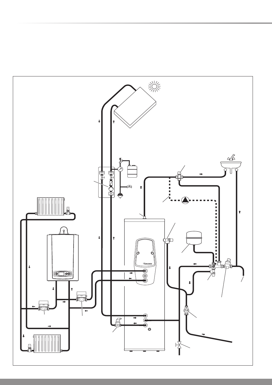
Hydraulic Plan 1
SOLAR COLLECTOR
BOILER
SOLAR COLLECTOR
CIRCUIT PUMP
AUTO AIR
SEPARATOR
MOTORISED
2 PORT VALVE
MOTORISED
2 PORT VALVE
FLOW
FLOW
HOT
WATER
CONNECTION
TUNDISH
THERMOSTAT
MIXER
FLUROCYL
DRAIN VALVE
RETURN
RETURN
EXPANSION
RELIEF
VALVE
(6.0 BAR)
PRESSURE
LIMITING VALVE
(3.5 BAR)
WITH LINE
STRAINER
COLD
WATER
SUPPLY
PUMP
EXPANSION
VESSEL
TEMPERATURE
AND PRESSURE
RELIEF VALVE
(95 °C, 7 BAR)
LEGIONNELLA
LOOP (optional)
4.1 Hydraulic plan
IMPORTANT: Reference cylinder instructions for wiring to
cylinder thermostats and thermal cut-outs.
(
NOTE: The Glow-worm Flurocyl cylinder is fitted with a solar
thermal cut-out - other manufacturers cylinders may not be
fitted with this device).
IMPORTANT: To simplify the system wiring, two hydraulic
plans are stored in the Fluropro solar control.
Hydraulic Plan 1 includes one collector array and
Hydraulic Plan 2 includes two collector arrays,
(separate circuits and pump stations). The relevant plan must
be selected within the Fluropro installer menu.