Introduction – Glow-worm Clearly Heat Pump 5 kW User Manual
Page 8
0020111744_00 - 09/10 - Glow-worm
- 6 -
INTRODUCTION
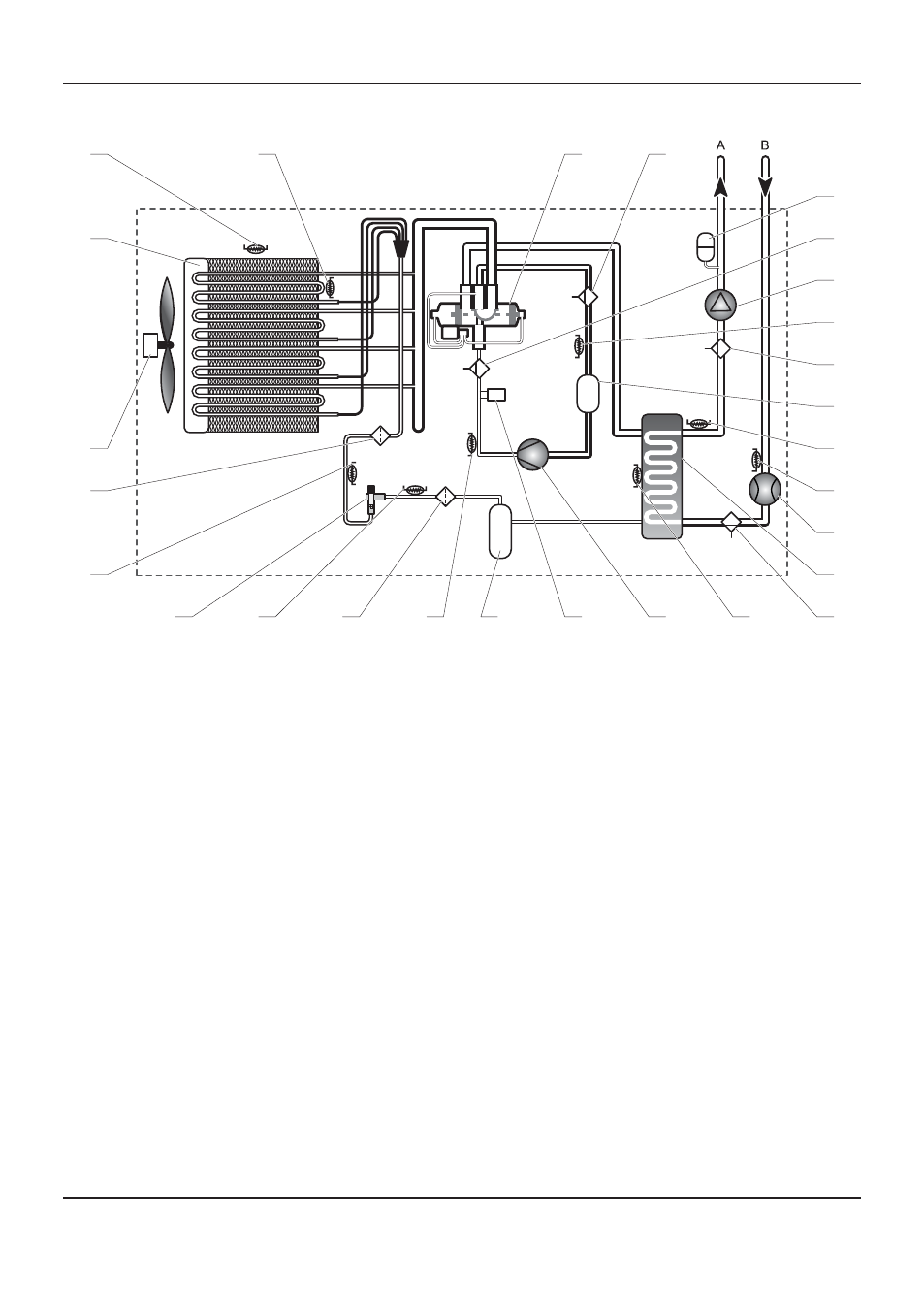
16 Return heat pump temperature sensor
17 Water
fl ow rate sensor
18 Exchanger with plates
19 Hydraulic circuit venting valve
20 Plate to plate heat exchanger temperature sensor
21 Scroll
compressor
22 High pressure cooling circuit sensor
23 Liquid
reservoir
24 Compressor discharge temperature sensor
25 Filter
26 Pre-expansion temperature sensor
27 Electronic pressure regulator
A Heat
pump
fl ow
B
Heat pump return
2.5
Hydraulic and refrigerant schematic
1
26
25
27
24
2
3
4
5
6
20
21
22
23
19
17
16
14
15
13
12
11
10
9
8
7
18
Key
1
Temperature sensor for detecting end of defrosting
2 Filter
3 Ventilating
fan
4
Tubular heat exchanger
5
Exterior ambient sensor
6 Air/refrigerant
thermistor
7
4-way reverse cycle valve
8
Low-pressure circuit maintenance valve
9 Expansion
vessel
10 High-pressure circuit maintenance valve
11 Pump
12 Compressor suction temperature sensor
13 Air
trap
14 Suction
accumulator
15 Outgoing heat pump temperature sensor
- 12-38hxi Range (44 pages)
- 18-30sxi Range (48 pages)
- 23c (44 pages)
- 24-38CXI Range (52 pages)
- 30ci Plus (56 pages)
- BBU 45/4 (32 pages)
- BBU 54/4 (32 pages)
- Betacom C (68 pages)
- Betacom2 (8 pages)
- Betacom2 (20 pages)
- Betacom2 (56 pages)
- Black Beauty 4 (20 pages)
- Chatsworth 4 (24 pages)
- Clearly Heat Recovery (20 pages)
- Clearly Heat Recovery (32 pages)
- Clearly Heat Pumps Envirosorb3 (28 pages)
- Clearly Heat Pumps Envirosorb2 (44 pages)
- Clearly Heat Pumps 7kW (44 pages)
- Clearly Heat Pumps 5kW (28 pages)
- Clearly Heat Pump 5kW (16 pages)
- Clearly Heat Pump - Buffer Vessel (10 pages)
- Clearly Heat Pumps - Standalone Module System (40 pages)
- Clearly Heat Pumps - Standalone System (28 pages)
- Clearly Hybrid - Universal Module (20 pages)
- Clearly Hybrid - Universal Module System (36 pages)
- Clearly Hybrid - Compact Hydraulic Module (12 pages)
- Clearly Hybrid - Compact System (36 pages)
- Clearly Hybrid - Compact Hydraulic Module HB (16 pages)
- Clearly Hybrid - Back-up Module System (40 pages)
- Clearly Solar System Hydraulics (28 pages)
- Clearly Solar System (28 pages)
- Clearly Solar Controller (28 pages)
- Clearly Solar Horizontal On-Roof Collector (16 pages)
- Clearly Solar Vertical On-Roof Collector (16 pages)
- Clearly Solar Cylinders (32 pages)
- Clearly Solar - A-Frame (28 pages)
- Clearly Solar Horizontal In-Roof Collector (32 pages)
- Clearly Solar Vertical In-Roof Collector (44 pages)
- Clearly Solar Collector Container (8 pages)
- Climapro 1 (12 pages)
- Climapro2 RF (16 pages)
- Climapro2 RF (24 pages)
- Climapro2 RF (36 pages)
- Climapro2 RF (32 pages)