Installation – Glow-worm Clearly Heat Pump 5 kW User Manual
Page 17
0020111744_00 - 09/10 - Glow-worm
- 15 -
INSTALLATION
Electrical components have been tested to meet the equivalent
requirements of BSEN 7671 and the BEAB regulations.
The cables connecting the switchboard and the heat pump must
be:
- Suitable for a fi xed installation.
- weather resistant.
- equipped with wires adapted to appliance’s power rating.
• Connect the heat pump to an electrical panel via an
independent protection system (20A differential breaker with
at least 3 mm between each contact).
Additional protection may be required during installation to
ensure surge category II.
11.1 Main
board
20 mm max.
1
2
Key
1 Electrical
wires
2 Insulation
When you connect the electrical wires to a connector on the
electronic board:
• Keep a distance of a maximum of 20 mm between connector
and the start of the insulation (2).
11.2 Access to main board
B
A
2
1
Key
1 Handle
2 Box
• Remove the box (2) by pulling it toward you using the handle
(1).
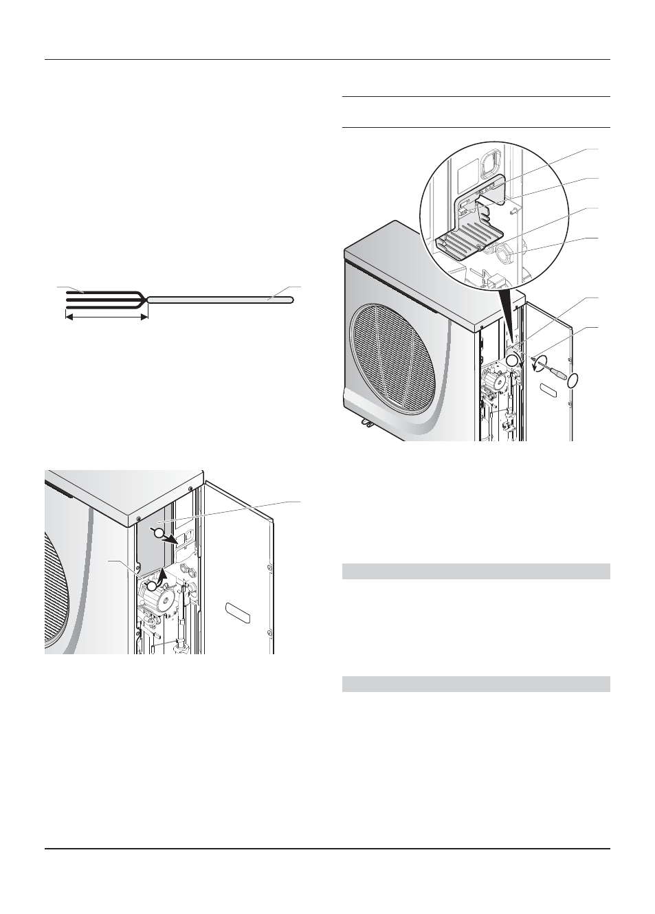
11.3 Electrical
wiring
e
Insert the Ebus 24V cable and 230V power cable
in different casings.
B
A
5
4
3
2
1
6
Key
1
230 V supply connection terminal block
2
BUS connection terminal
3
Gland for Ebus cable
4
Gland for 230 V power cable
5
Access hatch to electrical connections
6
Access hatch screw
• Remove the screw (6) from the access hatch (5).
• Open the access hatch (5).
Ebus Connection
• Connect a 2 x 0.75 mm ² cable to the appliance’s BUS
terminal (2).
• Pass the cable through the gland (3).
• Connect the Ebus cable to the system control unit.
• Tighten the gland.
230V Connection
• Connect a 3 x 2.5 mm ² cable to the appliance’s power
terminal 230 (1).
• Pass the cable through the gland (4).
• Connect the appliance’s power cable to the installation’s
electrical panel: single-phase network 230V + neutral +
earth.
• Close the access hatch with the screw (6).
• Tighten the gland.