Installation, 9 hydraulic connection, 10 evacuation of condensates – Glow-worm Clearly Heat Pump 5 kW User Manual
Page 16: 11 electrical connections
0020111744_00 - 09/10 - Glow-worm
- 14 -
INSTALLATION
9 Hydraulic
connection
• Take care to clean the pipes before assembly removing any
debris or burrs. Grease and oils may need to be removed
they are not possible to remove by cleansing and fl ushing.
Foreign bodies in the system may enter the appliance and
interrupt its operation.
• Do not use any solvent products, due to the risk of damaging
the circuit.
• Only use original seals supplied with the appliance.
b
Make sure that mechanical connections are not
overtightened.
• Comply with the values given in the table below when
making the hydraulic connections of the heat pump circuit.
Linear distance (without elbows or
additional pressure drops)
Min. diameter of tubes to
be installed
≤ 20 m
Ø ¾"
≤ 30 m
Ø 1"
9.5.1
Connection to the heat pump
b
Insulate the pipes with an UV- and high-
temperature-resistant insulation.
1m min.
4
2
1
3
5
6
7
8
key
1 Heat
pump
fl ow circuit ¼ turn shut-off valve in the direction of
the building (not included)
2
Return circuit ¼ turn shut-off valve in the direction of the heat
pump (not included)
3
Return circuit hose in the direction of the heat pump (not
supplied)
4 Cap
5
Return connection (Ø1 ") to the heat pump
6
Flow heat pump connection (Ø1 ") to the building
7
Flow heat pump circuit hose in the direction of the building
(not supplied))
8
Insulation (not supplied)
• Remove the protection caps (4) located on the connections.
• Connect a hose (3) and a shut-off valve (2) to the return
connection (5) to the heat pump.
• Connect a hose (7) and a shut-off valve (1) to the fl ow heat
pump connection (6) in the direction of the building.
• Check that there are no leaks. Repair if necessary.
• Insulate all exposed pipework.
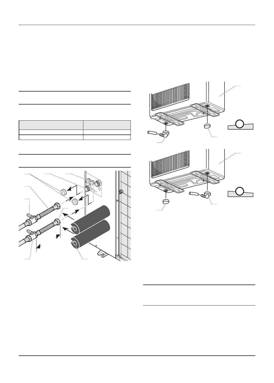
10 Evacuation of condensates
When the appliance is operational, it will produce condensation
that needs to be drained off.
1
2
3
A
1
3
2
B
Key
A Confi guration with inclination to the left
B Confi guration with inclination to the right
1 Heat
pump
2 Plug
3 Drainage
elbow
• Insert the drainage elbow (3) and pipe into the correct
opening depending on the angle of the heat pump.
• Seal off the other opening with the supplied plug (2).
11 Electrical
connections
e
Incorrect installation can cause electric shock or
appliance damage. The electrical connection of
the appliance must be made only by a qualifi ed
engineer.
The appliance must be connected directly to an accessible,
fi xed, switched, electrical outlet.
The manufacturer declines any responsibility for damages to
persons or others caused by the incorrect installation of the
appliance earthing. This includes failure to comply with current
standards.