Installation – Glow-worm Clearly Heat Pump 5 kW User Manual
Page 14
0020111744_00 - 09/10 - Glow-worm
- 12 -
INSTALLATION
7.2
Recommendations before installing
Installation pipework must be designed and installed to ensure
venting of air from the system is possible.
b
Ensure that the water fl ow rate of the water circuit
corresponds to the nominal water fl ow rate of the
appliance (see ¨Technical data¨ chapter).
• Install the following components on the rear section of the
heat pump
- a fi lter,
- a ¼ shut –off valve on each side of the fi lter,
- a drain valve,
- an air separator (if necessary)
- a sludge deposit (if necessary).
• Install a ¼ turn shutoff valve in the fl ow of the heat pump.
i
In order to avoid the transmission of vibrations to
surrounding structures, use hoses for the hydraulic
connections at least 1 metre from the heat pump.
b
Insulate the pipes with a UV- and
hightemperature- resistant insulation.
7.3 Dimensions
390
345
880
171
171
538
37
898
350
935
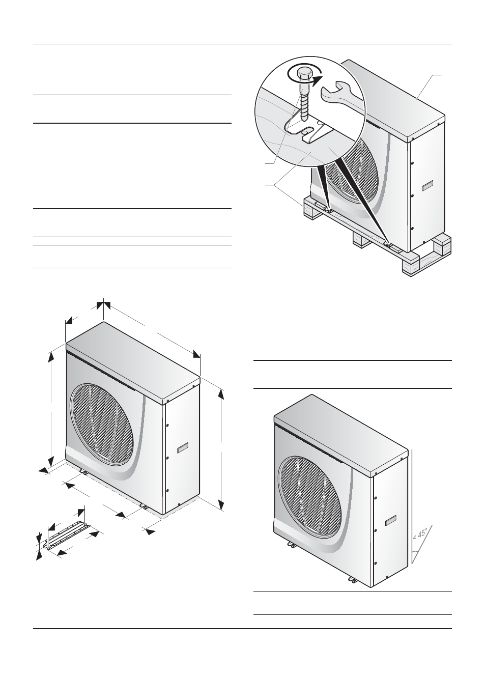
7.4 Mounting
7.4.1
Unpacking the appliance
• Carefully remove the packaging and protections without
damaging the parts of the appliance.
1
2
3
Key
1 Transport
pallet
2 Attachment
screws
3 Heat
pump
• Remove the screws from the transport pallet at the front and
rear of the unit.
7.4.2
Transportation of the appliance
i
With regards to the Manual Handling Operations,
1992 Regulations, the following lift operation
exceeds the recommended weight for a one man lift.
a
Warning! Two people at minimum are necessary
to move the appliance.