Installation, 16 user information – Glow-worm Clearly Heat Pumps 14kW User Manual
Page 36
0020117819_01 - 05/11 - Glow-worm
- 34 -
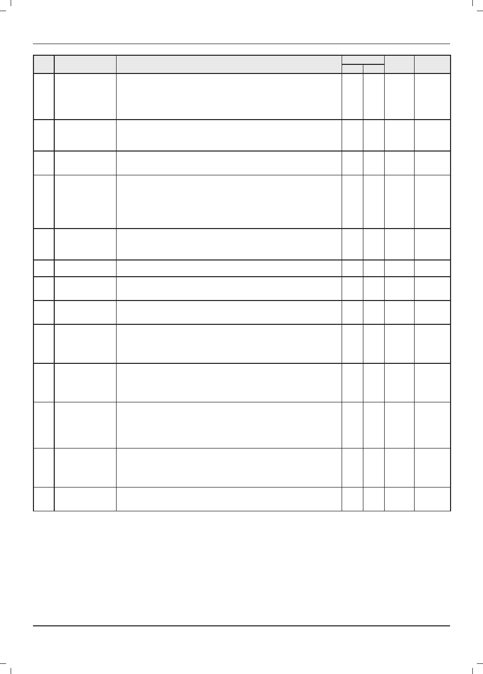
Code Function
Description
Setting
Factory
setting
Modifi able
parameter
Min
Max
146
Confi guration for
stopping the heat
pump if control by S1
contact input
1 = Immediate halt (as soon as contact S1 moves into the open position, the heat
pump stops).
2 = Gradual halt (as soon as contact S1 opens, the speed of the compressor
gradually reduces. This confi guration is used to delay the shutdown of the
compressor after contact S1 switches to the open position and to limit the number
of compressor cycles per hour to 3.
1
2
2
Yes
147
Confi guration of
the output between
terminal channels 5
and N
1 = Unit alarm
2 = Ambient temperature setting reached
1 2
1
Yes
148 Limit exterior
temperature (T0)
This parameter defi nes the exterior temperature that is the functioning limit and where
the heat pump stops. In this confi guration, only the booster heating functions. See the
chapter "Confi guring the booster heating".
-20°C 65°C
-20°C
Yes
149
Choice of display in
the command unit's
temperature zone
1 = Ambient temperature
2 = Temperature of water leaving the installation
3 = Temperature of water returning to the installation
4 = Temperature of the cooling fl uid in the plate to plate exchanger
5 = Compressor suction temperature
6 = Compressor discharge temperature
7 = Exterior temperature
1
7
1
Yes
150 Exterior temperature
bivalence point (T1)
This temperature defi nes the external temperature from which the power of the
heat pump alone is not suffi cient to meet the needs of the installation. Below this
temperature, the booster heating and the heat pump can function together. See
the chapter "Confi guring the booster heating".
30°C -20°C
0°C
Yes
151 Delays for switching
on booster heating
This parameter defi nes the period from which the booster heating is switched on
when: T0 < exterior T° < T1.
1
60
20
minutes
Yes
152 Diff erential stop/
start booster heating
This parameter defi nes the diff erential between the installation's water
temperature setting and the water temperature from which the booster heating
switches on when: T0 < exterior T° < T1.
1°C
20°C
5°C
Yes
153
Mode of activation
hot-water demand
contact S5
1 = Always active (demand for hot water is always met)
2 = Activated only in heating and cooling modes (demand for hot water is met only in
heating or cooling mode)
1
2
1
Yes
154 Booster heating
functioning
This parameter defi nes the functioning of the booster heating when: exterior T° < T0.
0 = Continuous functioning
1 = ON/OFF functioning depends on the ambient temperature.
In case of a thermostat fault, switch to mode 3.
2 = ON/OFF functioning depends on the installation's water temperature.
1
2
1
Yes
155 Functioning of main
circulator
This parameter defi nes the functioning mode for the main circulator for an external
temperature < T0 (code 148)
0 = Stopped
1 = ON/OFF cycle identical to the booster heating
2 = Continuous operation
0
2
1
Yes
156
Confi guration of
the output between
terminals 12 and N
Confi guration of the output (connection between terminal channels 12 and N)
0 = Not used
1 = ON/OFF cycle identical to the main pump The water pump works continuously
in case of demand for hot water.
2 = ON/OFF cycle identical to the main pump The pump is halted in case of demand
for hot water.
0
2
2
Yes
157 Functioning of the
additional circulator
This parameter defi nes the functioning mode for the additional circulator for an
external temperature < T0 (code 148)
0 = Stopped
1 = ON/OFF cycle identical to the booster heating
2 = Continuous operation
0
2
1
Yes
158
Diff erential on the
temperature setting
from the ambient air
This parameter defi nes the diff erential on the ambient temperature setting in the
case where the parameter 100 is confi gured to 4 (regulation with the command
unit used as the room thermostat).
+/-
0.2°C
+/-
1°C +/- 0.3°C
No
- advise the user of the precautions necessary to prevent
damage to the system, appliance and the building;
- remind the user to service the appliance annually.
- The user shall not interfere with or adjust sealed components.
- All servicing must be carried out by a competent person
approved at the time by the Health and Safety Executive.
16 User information
At the end of the installation, the installer must:
- explain the operation of the appliance and its safety devices to
the user, if necessary provide a demonstration and answer any
questions;
- hand over to the user all the required documentation,
- fi ll in the documents where necessary;
INSTALLATION