Installation, 11 hydraulic connection, 12 discharge of condensate – Glow-worm Clearly Heat Pumps 14kW User Manual
Page 24: 13 electrical connection
0020117819_01 - 05/11 - Glow-worm
- 22 -
11 Hydraulic connection
•
Take care to clean the pipes before assembly removing any
debris or burrs. Grease and oils may need to be removed they
are not possible to remove by cleansing and fl ushing. Foreign
bodies in the system may enter the appliance and interrupt its
operation.
•
Do not use any solvent products, due to the risk of damaging
the circuit.
•
Only use original seals supplied with the appliance.
b
Make sure that mechanical connections are not
overtightened.
b
Insulate the pipes (between the heat pump and the
installation including those underground) with an UV-
and high-temperature-resistant insulation.
1m min.
1
2
3
7
4
4
5
6
8
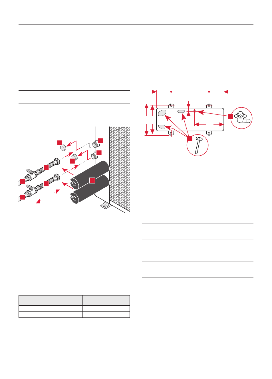
key
1 Heat
pump
fl ow circuit ¼ turn shut-off valve in the direction of the
building (not included) (*)
2 Return circuit ¼ turn shut-off valve in the direction of the heat pump
(not included) (*)
3 Return circuit hose in the direction of the heat pump (not supplied)
4 Cap
5 Return connection (Ø1 ") to the heat pump
6 Flow heat pump connection (Ø1 ") to the building
7 Flow heat pump circuit hose in the direction of the building (not
supplied))
8 Insulation (not supplied)
(*) To be installed as close as possible to the heat pump
•
Remove the protection caps (4) located on the connections.
•
Comply with the values given in the table below when making
the hydraulic connections of the heat pump circuit.
Max linear distance (without elbows or
additional pressure drops)
Tubes to be installed
≤ 20 m
¾" or Ø internal = 20 mm
≤ 30 m
1" or Ø internal = 26 mm
•
Connect a hose and a shut-off valve to the return connection to
the heat pump.
•
Connect a hose and a shut-off valve to the fl ow heat pump
connection in the direction of the building.
•
Install the fi lter on the heat pump return pipe. Install it
between 2 shut-off valves in order to be able to remove if from
the circuit and clean it periodically.
•
Insulate all exposed pipework.
12 Discharge of condensate
When the appliance is operational, it will produce condensation
that needs to be drained off .
1
2
600
150
150
430
400
363
37
Key
1 Evacuation bend for condensates
2 Holes pre-cut in the base of the heat pump
•
Install the bend (1) delivered with the appliance and connect it
to an evacuation pipe with an internal diameter of 16 mm (not
supplied).
•
Make sure that the condensates evacuation pipe does not
freeze.
The discharge capacity of the condensate increases if the pre-cut
holes (2) present in the base are open. Open the pre-cut holes
using a hammer.
i
If you choose to open the pre-cut holes (2) present in
the base, take the necessary precautions to recover
the condensates and stop them freezing.
13 Electrical connection
e
Incorrect installation can cause electric shock or
appliance damage. The electrical connection of the
appliance must be made only by a qualifi ed engineer.
The appliance must be connected directly to an accessible, fi xed,
switched, electrical outlet.
The manufacturer declines any responsibility for damages to
persons or others caused by the incorrect installation of the
appliance earthing. This includes failure to comply with current
standards.
Electrical components have been tested to meet the equivalent
requirements of BSEN 7671 and the BEAB regulations.
The cables connecting the installation's electrical panel and the
heat pump must be:
- Suitable for a fi xed installation.
INSTALLATION