Installation – Glow-worm Clearly Heat Pumps 14kW User Manual
Page 30
0020117819_01 - 05/11 - Glow-worm
- 28 -
14 Commissioning
i
At the time of commissioning, complete all relevant
sections of the Benchmark Checklist located on the
inside back pages of this document.
•
Check that the diff erential breaker is installed.
•
Check that the hydraulic and electrical connections are correct.
•
Check that the fi lter on the heat pump return is installed.
•
Check the airtightness of the connections.
•
Open all the hydraulic circuits’ valves.
14.1 Filling the glycol circuit
b
Warning! Do not dispose of glycol into drains and the
environment.
b
We recommend that you use propylene glycol
enriched with corrosive inhibitors.
•
Mix 1 part propylene glycol with 2 parts water. This 30%
mixture ensures antifreeze protection down to an exterior
temperature of -15 °C.
•
Use an antifreeze test kit to ensure accurate dosing.
•
Make sure that the hydraulic circuit is purged.
•
In order to drain the glycol circuit after fi lling, use a fi ll pump.
•
Put the heat pump circuit under pressure between 1.5 and 2 bars.
i
The level of glycol may decrease during the fi rst month
following the commissioning of the installation. It may
also vary in accordance with the outdoor temperature.
Any residue of glycol solution should be kept in an appropriate
container to be re-used for the next fi lling.
•
Ensure any leftover glycol solution is left with the end user and
retained in a safe place.
14.2 Activating the heat pump
e
Make sure that all the electrical connections have
been made.
b
Make sure that the setting for the maximum temperature
at heating fl ow is compatible with the installation.
•
Position the circuit breaker located on the electrical circuit box
and connected to the heat pump to the ON position.
The main screen for the command unit is displayed.
•
See the chapter "Example installation" to enter all the settings
corresponding to your installation.
14.3 Activating the options
•
See the instructions for each option to activate them and enter
their settings.
14.4 Heating system test
•
Ensure that there is a heating demand to the control unit. In
the case of a multi-zone confi guration, perform the test zone
by zone and ensure that the appropriate zone gets warmer.
•
Ensure that all the heating circuit’s thermostatic valves are
open.
•
Balance the heat emitters, if necessary.
15 Specifi c adjustment
15.1 Adjusting the heating circuit
b
The maximum heating output temperature must be
adjusted in accordance with the characteristics of
your installation.
b
Ensure that the heating curve setting is compatible
with the installation.
b
Make sure that the functioning mode for the boiler's
circulator is not in permanent mode, but synchronised
with heating demand (with the room thermostat).
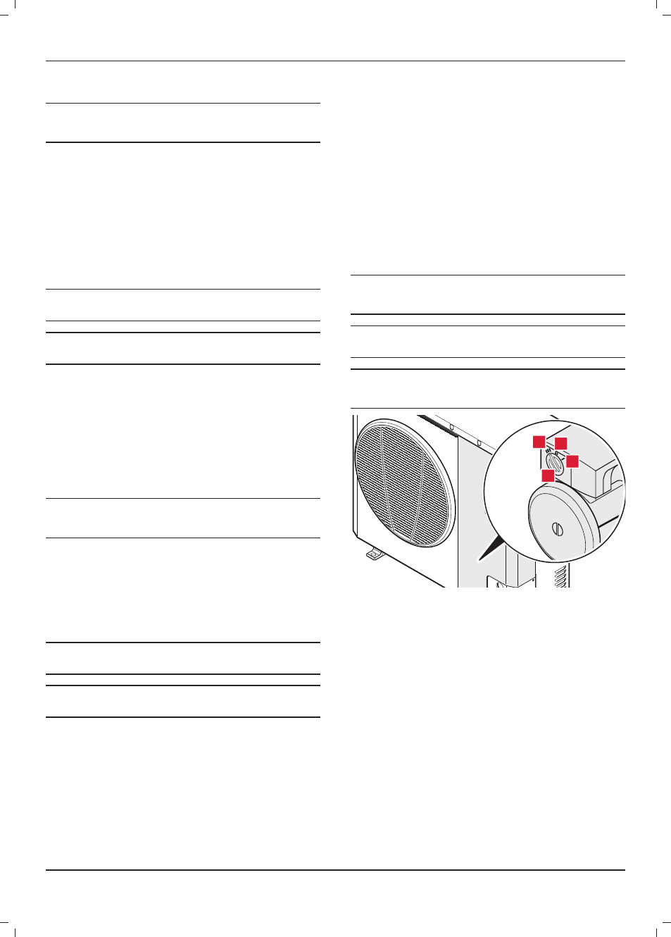
2
4
3
1
Key
1 Speed
I
2 Speed
II
3 Speed
III
4 Speed
selector
•
Turn the circulator's speed selector to choose speed I.
•
Open all the thermostatic valves on the radiators to the
maximum.
•
Adjust the temperature to the maximum on all the room
thermostats in your home.
•
Put your installation into service by forcing a heating request
when the circulator should start.
•
Wait 10 to 15 min and measure the diff erence in temperature
between fl ow and return of the heat pump (temperatures can
be displayed using parameters 137 (return) and 138 (fl ow)).
The diff erence should be between 5 and 6°C.
•
If the diff erence is greater than 6°C, select a higher pump
speed or reduce the circuit pressure drops.
INSTALLATION