Installation – Glow-worm Clearly Heat Pumps 14kW User Manual
Page 17
0020117819_01 - 05/11 - Glow-worm
- 15 -
2.3
Protection against the sharp edges of the sheet metal
for the cable passage (if necessary)
(x1)
2.4
Leak-tight seal for the cable passage (if necessary)
(x1)
3
Packet of documents
(x1)
3.1 Installation
manual
(x1)
3.2
Instructions for use
(x1)
4
Command unit
(x1)
•
Check the contents of the package.
9.2
Recommendations before installation
9.2.1
Design of the heating circuit
The heat emitters may be either low temperature (underfl oor
heating, etc.), or medium temperature (warm radiator, etc.).
b
We recommend that you provide suffi cient fl ow for the
temperature diff erence between fl ow and return to
be equal to 7 C for a underfl oor heating and 15 C for
radiators.
The route of the piping will be designed to take all measures ne-
cessary to avoid air pockets and facilitate the permanent venting
of the installation. Vents must be provided at each high point of
the pipes, and on all the radiators.
b
Always leave a radiator open.
We recommend installing a drainage valve at the lowest point of
the installation.
In the case of the use of thermostatic valves, it is imperative not
to fi t to all radiators, taking care to fi t these valves in rooms with
high input and never in rooms where the room thermostats are
installed.
- If it is an old installation, it is essential to rinse the radiator
circuit before installing the new appliance and to add an anti-
sludge fi lter.
- If a component of the system is not to be installed
immediately, protect the various connections so plaster
and paint cannot compromise the seal on the subsequent
connection.
•
Install the following components on the heating circuit return:
- a heating fi lter,
- 2 quarter-turn shut-off valves (1 each side of the fi lter),
- an air separator (if necessary),
- an anti-sludge fi lter (if necessary).
•
In the case of a underfl oor heating, install a security device to
prevent overheating, with manual reset (55°C) on the heating
circuit fl ow. Connect the overheating security device to the
glycol pump of the heat pump.
9.2.2
Design of the heat pump circuit
Installation pipework must be designed and installed to ensure
venting of air from the system is possible.
b
Ensure that the water fl ow rate of the water circuit
corresponds to the nominal water fl ow rate of the
appliance (see ¨Technical data¨ chapter).
•
Install the following components on the rear section of the
heat pump:
- a fi lter,
- a ¼ shut –off valve on each side of the fi lter,
- a drain valve,
- an air separator (if necessary)
- a sludge deposit (if necessary).
•
Install a ¼ turn shutoff valve in the fl ow of the heat pump.
i
In order to avoid the transmission of vibrations to
surrounding structures, use fl exible hoses for the
hydraulic connections at least 1 metre from the heat
pump.
b
Insulate the pipes with a UV- and hightemperature-
resistant insulation.
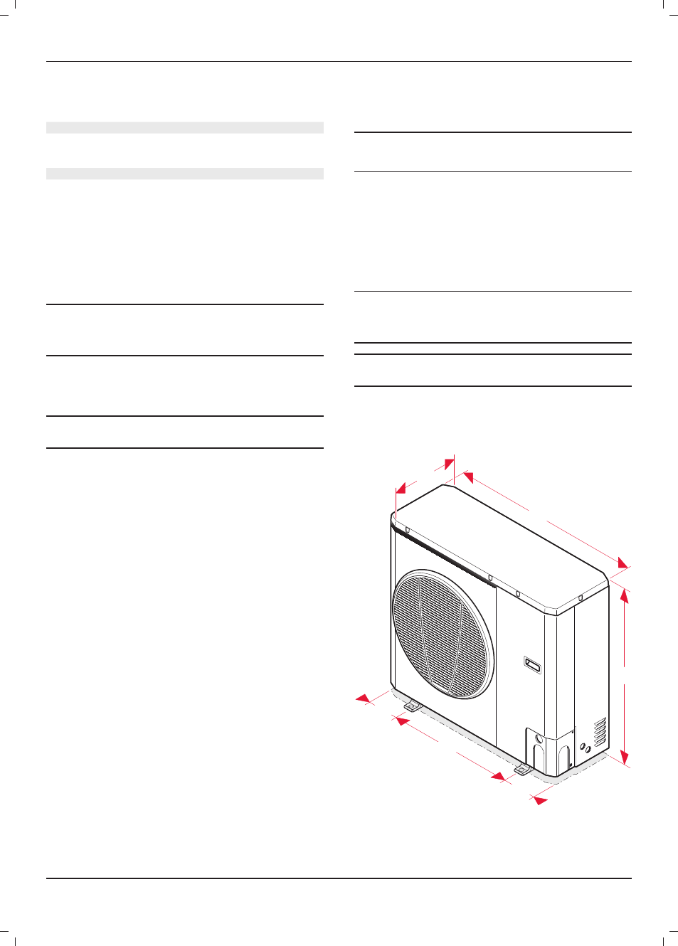
9.3 Dimensions
9.3.1 Envirosorb
7
150
150
600
908
326
821
INSTALLATION