FeiYu Tech FY-DOS User Manual
Page 4
Guilin Feiyu Electronic Technology Co., Ltd
Guilin Feiyu Electronic Technology Co., Ltd http://www.feiyudz.cn E-mail: [email protected] Page 4
GPS module interface
The GPS pin interface consist of: GND, +3V , RX0. The characteristics are:
Baud rate: 38400
Data bits: 8
Stop Bits: 1
Parity: None
Interface Features: TTL level
Connect the above to the GPS Receiver. The GPS data protocol is a standard NEMA0183 and the statement must be
$ GPRMC, $ GPGGA.
TXO pin interface is used to output DoS data, and connect Hornet-OSD(V1.6 edition).
Data Radio interface
The UART pin interfaces consist of: GND, power 5V , TX1, RX1. The characteristics are as follow:
Baud Rate: 19200
Data bits: 8
Stop Bits: 1
Parity: None
Interface Features: TTL level
The pin interfaces connects to the Data Radio, PC computer serial port or OSD module. You can set DoS control
parameters through this interface. The port is also used to upgrade DoS firmware. Please read the procedure for the
firmware upgrade.
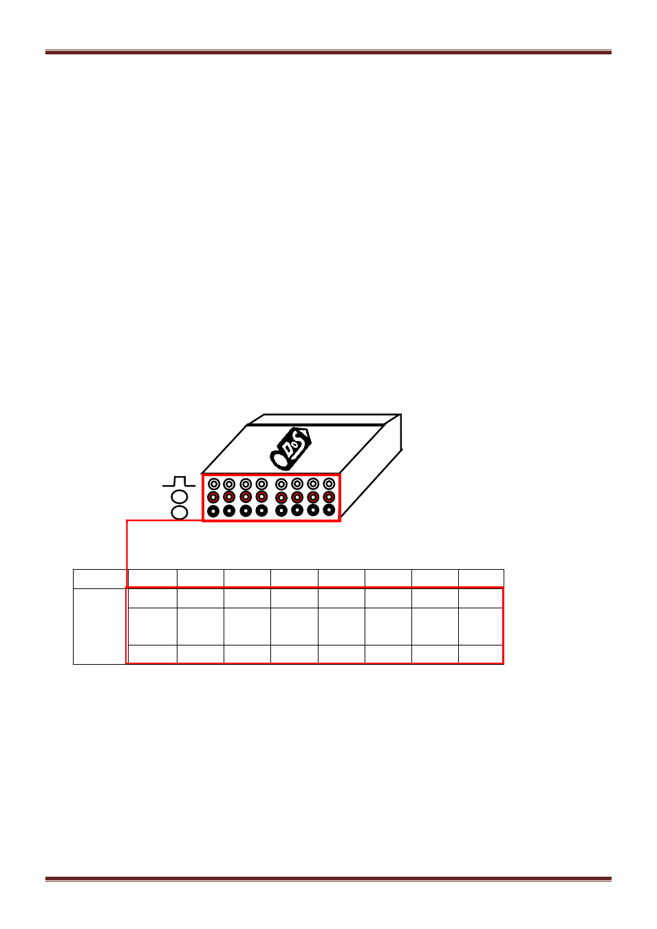
Servo output interface
No.
S8
S7
S6
S5
S4
S3
S2
S1
Servo
Output
Interface
P2
P1
N
AIL2
RUD
THR
ELE
AIL
Power
+5V
Power
+5V
Power
+5V
Power
+5V
Power
+5V
Power
+5V
Power
+5V
Power
+5V
GND
GND
GND
GND
GND
GND
GND
GND
V1.1 firmware servo output introduction
S1: connection aileron servo 1(same signal as S5).
S2: connection elevator servo.
S3: connection ESC or throttle servo.
S4: connection rudder servo.
S5: connection aileron servo 2 (without setting mix control ,same signal as S1)
S6: not used
S7:When use Remote Adaptor, CH7 receiver output channel (detail please reference Remote Adaptor and Data Radio
introduction)
S8: When use Remote Adaptor, CH8 receiver output channel (detail please reference Remote Adaptor and Data Radio
introduction)
Plane connecting layout
1)connection for traditional aircraft layout:
S2 S1
S3
S4
S5
S6
S7
S8
-
+